Transformer Performance & Electrical Parameters Calculation
Rated Power of Transformer
Rated Power is the amount of power that a transformer can handle and it is limited by the size of the winding conductors, and by the corresponding amount of heat they will product when current is applied.
This heat is caused by losses, which results in a difference between the input and output power. Because of these losses, transformers are rated not in terms of kW or MW (active power), but in terms of kVA or MVA (apparent power).
Rated Power is noted as “S”.
If a transformer as two cooling systems Rated Power of the transformer depends of the cooling method that is in use in a certain moment, and so at the name plate of the transformer two Rated Powers are indicated.
Considering a transformer with an ONAN / ONAF (Oil Natural Air Natural/Oil Natural Air Forced) cooling system, Rated Power of this transformer is, for example 30/40 MVA, 30 MVA corresponding to ONAN and 40 MVA corresponding to ONAF.
- Related Article: Power Transformer Protection & Faults
Rated Voltages, Ratio & Rated Frequency of Transformer
Rated Voltages of a transformer are the service voltage of the primary and of the secondary, V1 and V2, respectively.
The ratio of a transformer is the relation between the number of turns of primary winding and the number of turns of the secondary windings, and is noted as “a”.
Considering a transformer with N1 turns in the primary winding, N2 turns in the secondary winding, V1 and V2 the primary and the secondary voltages, and I1 and I2 the primary and the secondary currents, the ratio can expressed by the following equation:
a = N1 / N2 = V1 / V2 = I2 / I1
The rated frequencies are usually 50 Hz and 60 Hz.
Losses & Efficiency in Transformer
Transformers are subject to two types of losses:
- PCu : resistive losses (W)
- P0 : iron losses or core losses (W)
The resistive losses, due to Joule effect on the windings, depends on the current that goes through the turns of the windings, which results from the loads connected to the transformer.
The iron losses, are the sum of hysteresis losses and eddy current losses, which happens even when the transformer has no load (due to this fact iron losses are also known as no-load losses).
Both resistive losses and iron losses are indicated by the transformer’s manufacturer.
It is common that transformers that are not in service permanently (example: public lighting transformers) are required to have reduced iron losses.
Also Read: Maintenance of Transformer – Power Transformers Maintenance, Diagnostic & Monitoring
Total losses (Pt) are given by the equation:
Pt = P0 + PCu (W)
Iron losses are determined from open circuit test and resistive losses from short circuit test.
Efficiency of a transformer (noted “η” and expressed in “%”) is defined as the ratio between the input and the output active power.
Considering a transformer with the following parameters:
- Input : P1 ; V1, I1
- Output: P2 ; V2, I2
- Load power factor : Cos Φ
Efficiency is then calculated according to the following equation:
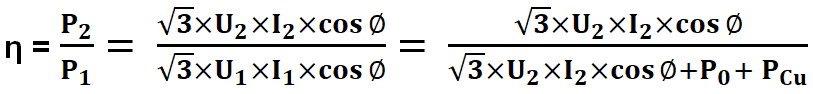
Hence at any volt-ampere load, the efficiency depends on power factor; at unity power factor efficiency has its maximum value.
Impedance Voltage Drop in T/F
Impedance voltage drop of a transformer represents the internal resistance of the transformer, and is usually noted as “uk” and indicated in “%”.
The equivalent impedances of the transformer are calculated by the equations:
Primary side
ZT = uk(%) x U12 / 100 x Sn
Secondary side
ZT = uk(%) x U22 / 100 x Sn
The values of the equivalent resistance and reactance of the transformer are given by the following equations:
RT = PCu / 3xIn2
![]() Related Post: What is the normal or average life expectancy of a Transformer ?
Related Post: What is the normal or average life expectancy of a Transformer ?
Vector Group of Transformers
Vector group of three-phase transformers indicate the phase shift between primary and secondary voltages and the way the windings are connected.
Three-phase windings transformers can have “star” (Y/y), “delta” (D/d) [ In delta connection, windings are connected in triangle, so it is usual to represent this connections by Δ] and “interconnected star” / “zigzag” (Z/z) connections, being the most common star and delta.
If the transformer has tertiary windings, usually for harmonic compensations, (mainly 3rd harmonic) these windings have a “delta” connection.
Capital letters refer always to highest voltage and lower-case letters to lowest voltage.
When neutral point is accessible letter “N” or “n” is added to the symbol.
Table 1 shows the most common vector groups.
Table 1 – Common vector groups
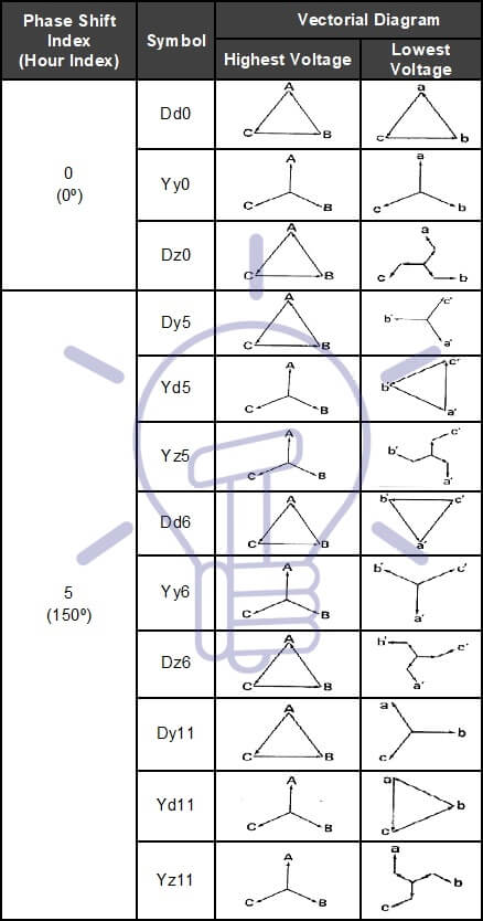
Most common connections are Y-Δ, Δ-Y, Δ-Δ and Y-Y; star-star is common in EHV and HV, although it presents imbalance and 3rd harmonic problems, being necessary the third winding above referred.
Star-Delta (Y-Δ) is frequently used as step down (EHV/HV); delta-delta (Δ-Δ) is commonly used for medium voltage (MV/MV transformers); delta-star (Δ-Y) is used in step-up transformer in a generation station and in MV/LV transformers.[EHV: Extra High Voltage (V ≥ 150 kV). HV: High Voltage (60 kV ≤ V < 150 kV). MV: Medium Voltage (1 kV < V < 60 kV). LV: Low Voltage (V ≤ 1 kV)]
Common groups in MV/LV power transformers are Dyn5 and Dyn11; for HV/MV power transformers is usual to have a vector group YNd11, and for HV/HV transformers is common to have YNyn0 and Ynyn1.
Voltage Regulation of Transformer
Electrical networks may have voltage fluctuations, due to load changing, network configuration and level of energy production.
For that reason is necessary to proceed to voltage regulation; Transformer regulation is done usually at the highest voltage windings of power transformers (because the current is lower).
Those windings must be provided with taps, voltage regulators and tap-changers.
At MV installations transformers have usually 5 taps (central point that corresponds to rated voltage and± 2×2.5 %taps) and off-load tap changer. The ratio of the voltages of the transformer is so defined as:
33 ± 2×2.5 % / 6.6 kV
At HV installations transformers have several taps, including the central point and on-load tap changer (OLTC) that can me manually and locally or remote operated or automatic operated through the Control and Monitoring System.
The ratio of the voltages of the transformer, taking into account the number of taps and their range, may be defined as:

The post Transformer Performance & Electrical Parameters appeared first on Electrical Technology.
July 29, 2018 at 04:26PM by Department of EEE, ADBU: https://ift.tt/2AyIRVT