Electrical Protection Units And Systems
This is a long and descriptive article on different types of protection for electrical systems and networks. In this article, you will be able to cover the different electric protection methods, system and devices, grading and protection, overhead lines protection, power system protection, cables feeder protection, transformer protection, motor protection ,generator protection, capacitor banks protection, bus bar protection, voltage and frequency protection and much more. Bookmark this post in case for later read.
Introduction to Electrical Protection Systems
HV, MV and LV[1] electric installations and equipments are subjected to internal and external faults that can cause serious damages in persons and other equipments.
To avoid and to minimize the consequences of those faults protection devices associated to equipments that are able to break electric current are required.
For a better understanding of protections devices, at each Section that covers protection systems of equipments and installations most common faults on those equipments and installations.
It is also important to refer that all units of mechanical and electrical parameters and their multiples and submultiples that are involved in the protection systems are in accordance with SI (Internation Units System); exceptions are made when hours (h) may be used instead of seconds (s) and the unit choosen for temperature is °C (celsius) instead of K (kelvin) – [K] = [°C] + 273.15.

Protection Devices and Technology
Protection Devices
In order to minimize the time of a fault switchgears and equipments are provided with protective devices to detect them and to isolate the faulty part of installation.
It is required firstly, the early detection and localization of faults, and secondly, the prompt removal from service of faulty equipment, in order to:
- To safeguard the entire system to ensure continuity of supply.
- To minimize damage and repair costs.
- To ensure safety of personnel.
In the past fuses were commonly used as a protection against overcurrents and overloads, and are still very popular in North America and in some countries they are still used in LV installations and in MV cables and transformers with rated power up to 630-1250 kVA.
However, complexity of networks and requirements for more reliable power transmission and distribution call for use of more accurate protection devices.
Protection relays are used nowadays, being more reliable and accurate and with the ability to detect other type of faults than overloads and overcurrents that can occur in networks and equipments, which will be discussed at further sections, when protection of equipments will be analyzed.
They are set to operate, and initiate tripping, when a fault condition is detected.
Each power system protection scheme is made up from the following components:
- Fault detecting or measuring relays
- Tripping and other auxiliary relays
- Circuit breakers
- Instrument transformers – current (CT) and voltage (VT)
First models of protection relays were electromechanical relays that are still in use in some countries and in old installations that were not subjected to renoval works.
They were attracted armature types, where the instrument transformers secondary output is passed through a coil, thus attracting the armature against spring tension. The movement of the armature causes the relay tripping contact to close.
Figure 1 shows an example of this type of relays.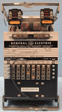
Figure 1 – Electromechanical protection relay
Nowadays electronic (solid-state) and microprocessor-based protection relays are commonly used in electrical utilities.
Electronic relays have only one protection function and different relays shall be used for different functions.
Microprocessor-based relays have many features available such as protection, control and monitoring.
Intelligent Electronic Devices (IED)
Microprocessor-based relays are known as Intelligent Electronic Devices (IED), which can provide 5-12 protection functions, 5-8 control functions controlling separate devices, an autoreclose function, self monitoring function and communication functions, being main their features:
- Many functions in a single relay
- Group settings readily changeable for changes in feeder configuration
- Programmable output relays
- Communication ports for connection to SCADA – Supervisory Control and Data Acquisition (Systems, Modems, and Personal Computers)
- Sequence-of-events stored for many recent faults
- Oscillography or waveform capture — storage of pre and post-fault current and voltage waveform data for analysis of faults
- Measurements
- Interlocking
- Aid to circuit breaker maintenance. Fault interrupting duty, per phase, can be recorded
- Fault Locater — Displays distance to fault
In the Figure 2 is possible to see an example of an IED.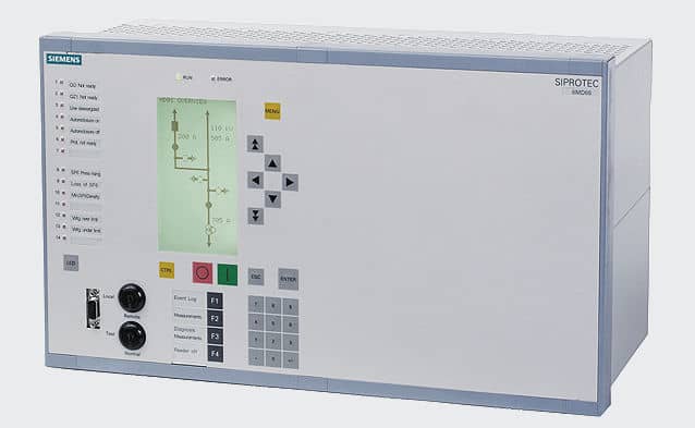
Figure 2 – IED
Functions and complexity of IED must be defined according to equipment to be protected, the networks characteristics and complementary actions required.
Actual IED are designed to fulfil the requirements of IEC[2] Standard 61850, which communication protocol is used. This standard was specifically developed for substation automation and provides interoperability and advanced communications capabilities.
The growth in the number of protection, control and monitoring points results a significant increase in the volume of substation data.
This data is usually primitive and stored in a digital form. It has to be processed and analyzed before any user is able to utilize the benefit of it.
In conventional protection system data and control signal from the relay are sent via an RTU (Remote Terminal Unit) to the SCADA system.
Extensive and costly cables may be required between various bays in the substation and the control room.
In modern protection system utilizing an IED relay the interconnection wiring between transducers and meters is no longer required.
The data and control signals from the IED relay are sent directly to the SCADA system via the high-speed dedicated communication network. The volume of data increases drastically when an IED is used as the control element and data source.
To provide the necessary connectivity between the various components of the system, a data network LONWORKS Local Operating Network (LON) is utilized.
IEC Standard 61850 defines the required protocols for communication, which can run over TCP/IP networks or substation LAN using high speed switched Ethernet to obtain the necessary response times below four milliseconds for protective relaying.
Protection Relays and Codes
In MV and HV substations, equipments, switchgears and power plants the more usual protection relays are indicated below, and between brackets is shown their code in accordance with IEEE/ANSI[3]/IEC Standards:
- Bearing protection (38)
- Breaker failure protection (50 BF)
- Bus bar differential protection (87B)
- Directional earth overcurrent (67N/67G)
- Directional phase overcurrent (67)
- Instantaneous earth overcurrent (50N/50G)
- Instantaneous phase overcurrent (50)
- Loss of field/excitation protection (40)
- Loss of phase (48)
- Over-excitation protection (24)
- Overfrequency and underfrequency (81)
- Overhead line differential protection (87L)
- Overhead line distance protection (21)
- Overload protection (49)
- Overspeed protection (12)
- Overvoltage (59)
- Restricted earth fault (64G/64REF)
- Reverse power protection (32)
- Time delay earth overcurrent (51N/51G)
- Time delay phase overcurrent (51)
- Transformer differential protection (87P)
- Undervoltage (27)
- Weak end infeed (21WI)
- Wrong phase sequence protection (47)
Mainly in HV overhead lines, HV power transformers and MV power transformers with rated power above 3-4 MVA, in order to increase system reliability and safety, is a common practice to use two sets of protections – one “main protection” and one “back-up protection”.
Protection with Fuses
A fuse is a type of low resistance resistor that acts as a “sacrificial device” to provide overcurrent protection that is still used in some LV and MV installations.
Its essential component is a metal wire or strip that melts when too much current flows, which interrupts the circuit, so that further damage by overheating or fire is prevented.
The metal strip or wire as a small cross-section compared to the circuit conductors and is enclosed by a non-combustible housing (casing).
The fuse element is made of zinc, copper, silver, aluminum or alloys to provide stable and predictable characteristics.
Casing may be of ceramic, glass, plastic, fiberglass, molded mica laminates or molded compressed fiber depending on manufacturer, application and voltage class.
Fuses are mounted on fuse holders, specifically designed for each type or family of fuses and rated voltages such as HRC fuse.
Examples of fuses and holders are shown in Figures 3 and 4.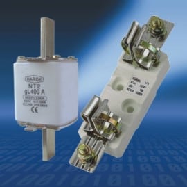
Figure 3 – LV NH type fuse and holder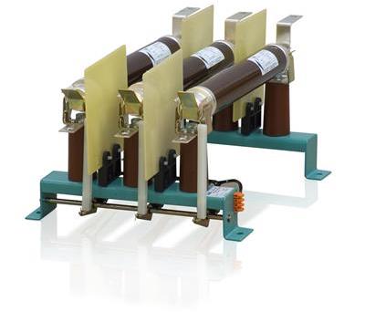
Figure 4 – MV fuses and holder
Main electrical characteristics of fuses are:
- Rated voltage
- Rated current (In): maximum current that the fuse can continuously conduct without interrupting the circuit.
- Breaking capacity (I1): maximum prospective current that the fuse can interrupt. It is the maximum fuse test value. This current is very high, generally between 20 kA and 63 kA.
- Minimum interrupting current (If): minimum current that can blow and interrupt the fuse
- Conventional non-fusing current (Inf): Value of current specified as that which the fuse-link is capable of carrying for a specified time (conventional time) without melting, expressed as a multiple of In (e.g. Inf = 1.25xIn)
- Nominal melting (I2t): measure of the energy required to melt the fusing element (based on Joule law) and is a value that is constant for each different fusing element.
- Time-current curve: shows the actuation time of the fuse (speed) as a function of the current (is usually indicated by manufactures, according to the standards)
Figure 5 shows an example of a time-current curve.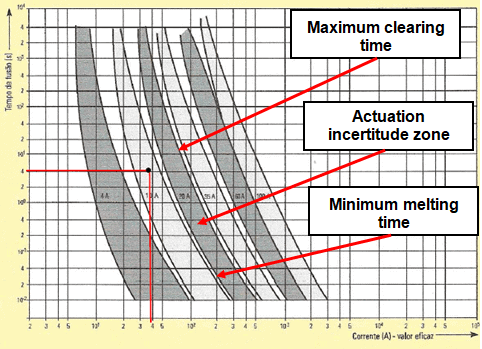
Figure 5 – Fuses time-current curve
Ambient temperature will change a fuse’s operational parameters and a temperature derating is necessary.
As an example a fuse rated for 1 A at 25 ºC may conduct up to 10% or 20% more current at -40 ºC and may open at 80% of its rated value at 100 ºC.
Operating values will vary with each fuse family and are provided in manufacturer data sheets.
The main selecting factors for a fuse are:
- Normal operating current
- Rated voltage (AC or DC)
- Ambient temperature
- Overload current and length of time in which the fuse must open
- Maximum available fault current
- Pulses, surge currents, inrush currents, start-up currents, and circuit transients
- Physical size limitations, such as length, diameter, or height
- Fuse features (mounting type/form factor, ease of removal, axial leads, visual indication, etc.)
- Fuse holder features, if applicable and associated rerating
- Application
- National wiring regulations and standards
French Standard NF EN 60269 classify fuses according to time-curves, functions and applications.This classification, largely used on many countries, is:
- gL/gG
- Functions
- Protection of cables and electrical devices. Discrimination ensured between two fuses or which there is a margin of two current ratings (e.g. 160 A and 100 A)
- Applications
- Protection at all levels of electrical distribution against overloads and short circuits. Main switchboard, feeder switchboards, main cubicles.
- aM
- Functions
- Direct protection of motors, must operate in conjunction with an external protection device (thermal relay). Easy discrimination with the gG fuses positioned upstream. Discrimination ensured between two fuses where there is a margin of two current rating (e.g. 160 A and 100 A)
- Applications
- Protection of low voltage motors.
- gR
- Functions
- Ultra fast protection fuse for semi conductors, very current limiting, low l2xt
- Applications
- Power semi conductor protection of soft starters, static relays, uninterruptible power supplies (UPS), variable speed drives, frequency
When an installation is protected by fuses, switch-disconnectors upstream of fuses must be used for safety reasons, to assure the isolation of the installation prior to replace a fuse or perform some maintenance works.
With a protection only with fuses is used, only phase overcurrents will be detected, and it is necessary to foreseen protection relays for other faults. For leakage current or ground fault current, GFCI (Ground Fault Circuit Interrupter) then used.
In this situation switches must equipped with an opening coil, which will be also actuated by the internal protection of the equipments.
Another precaution is that fuses must be provided with a mechanical device (striker pin) that will cause the switch to open, if only one fuse will act, to assure the total disconnection of the installation in fault.
Fuses shall also be provided with a coloured disc that falls out when the element is blown or an element window, built into the fuse body to provide visual indication of a blown element.
Grading and Protection Coordination
Introduction to Grading and Protection
When defining set-points of protection relays or rated current of fuses and LV circuit breakers (Such as ACB (Air Circuit Breaker)) it must be assured that the chosen values are suitable for the protection of the equipment and that the circuit breaker that trips or the fuse that will blow is only the one associated to the faulty circuit and not other protective devices, what could cause serious disturbances in the network and in quality and continuity of service.
To achieve this objective a grading and protection coordination study is required.
Basic Principles
Protection relay coordination studies are undertaken, to determine protection relay settings.
Fault levels have to be determined for all possible system operating conditions, this being used to determine the protection relays ability to detect and clear system faults.
The protection schemes are set to so as to isolate the least amount of the electrical system as possible, thus minimizing the disruption caused by the fault.
The protection relay clearance times are determined to meet primary plant short time rating, systems stability requirements and statutory authority requirements. We take care to determine the correct protection relay operating margins, both in current and time, so as to effectively eliminate malgrading.
When setting distance relays on double circuit high voltage feeders the zero sequence mutual coupling between the circuits is taken into consideration so as to minimize the possibility of over or under reaching occurring.
Relay operating characteristics and their setting must be carefully coordinated in order to achieve selectivity.
The aim is basically to switch off only the faulted component and to leave the rest of the power system in service in order to minimize supply interruptions and to assure stability.
Selectivity, or discrimination, between protection devices can be defined as “the coordination of the protection devices, in order for a fault that occurs at any point in the network to be eliminated by the upstream protection device, the protection device that is immediately upstream of the fault and by that protection device alone”.
Let us see an example of this definition looking the single line diagram of Figure 6, where there are protections systems SP1 to SP6: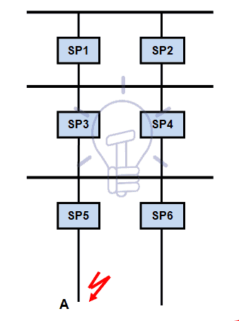
Figure 6 – Electrical installation single line diagram
Selectivity means that if a fault occurs at point A, the only protection system that should actuate is SP5 and that the other protection systems must not actuate.
Two principles are used to establish selectivity:
- Current discrimination.
- Time discrimination.
Grading and Protection Coordination in LV, MV and HV Networks
To establish grading and protection coordination studies it must be taken into account the configuration and the complexity of the network.
LV distribution and users networks have usually a radial configuration.
MV distribution networks have usually a combination of both radial and double-end feed with NO point configurations and an important complexity.
Users MV networks have usually a radial configuration, although in major plants a double-end feed with NO point configuration is used.
Due to the complexity of the networks grading and protection coordination studies for HV transmission networks and MV distribution networks, specialized engineers are required and the use of particular software tools for network analysis like ETAP, PSS/E, EPSO and PTW.
Grading and protection coordination studies of MV users’ network are usually easier and may follow the basic instructions that will be discussed later in this Section.
A particular attention must be observed in the boundary of electric distribution company network (infeeding) and users’ network and protection coordination protocol must be established between both entities.
For LV networks, using circuit breakers and/or fuses the selectivity of “circuit breaker/circuit breaker”, “fuse/fuse” and “circuit breaker/fuse” may be done by comparing “time-current curves” for a certain value of the fault current, using the principles of “current discrimination” and “time discrimination”, referred above.
Current discrimination is used for protection against overloads and the protection is selective if the ratio between the setting thresholds is higher than 1.6.
Time discrimination is used for the protection against short-circuits, using an upstream circuit breaker or fuse with a time delay and so tripping of the downstream device is faster; the protection is selective if the ratio between the short-circuit protection thresholds is no less than 1.5.
Overhead Lines Protection
Common Faults in Overhead Lines
The most common causes of faults in overhead lines are:
- Aircraft and cars hitting lines and structures
- Birds and animals
- Contaminated insulators
- Ice and snow loading
- Lightning
- Partial discharges (corona) not controlled
- Punctured or broken insulators
- Trees
- Wind
Overhead Lines Protection Devices
LV overhead lines are protected against overcurrents using fuses or circuit breakers.
Protection of MV overhead lines is usually achieved by overcurrent relays (50; 50N; 51; 51N; 67; 67N) connected to CT.
Time-graded overcurrent protection cannot be successfully applied to HV overhead transmission lines because there are usually many interconnected sources of fault currents which may be limited by fault current limiter.
The requirements of protection schemes for HV overhead transmission lines are:
- The protection system must be able to detect all faults on the protected line.
- The protection system must be able to discriminate between faults on the protected line and faults on adjacent lines, buses, transformers, etc.
- The protection system must be able to clear faults very quickly, (i.e. in less than 1 s) before the power system goes unstable.
- The protection system must be dependable, and must be capable of clearing faults when any single piece of equipment has failed.
To accomplish these requirements common protections devices used in HV overhead lines are:
- Differential and phase comparison protection
- Distance protection
Differential protection is mainly used on short overhead lines and distance protection on long overhead lines.
The distinction between short and long overhead lines is based on a comparison between the inductance and the resistance and capacitance of the overhead line.
When both resistance and capacitance are negligible when compared with the inductance, the over head line is considered short.
This comparasion is usually done usig the π diagram of the overhead line.
Voltage level, physical construction of the transmission line, type of and size of conductors and spacing of conductors determines the impedance of the line, and the physical response to short circuit conditions, as well as line charging current.
In addition, the number of line terminals determines load and fault current flow, which must be accounted for by the protection system.
Parallel lines also impact relaying, as mutual coupling influences the ground current measured by protective relays.
The presence of tapped transformers on a line, or reactive compensation devices such as series capacitor banks or shunt reactors, also influences the choice of protection system and the protection device settings.
Due to this reasons a detail study of the overhead line is required to choose the most suitable protection relays to be used.
However it is usual to consider a short line to have a length up to 80-100 km, depending on the voltage level and the characteristics of the network.
About 90% of overhead line faults are transient and faults may be:
- Phase-to-earth
- Phase-to-phase
- Phase-to-phase-to-earth
- Three-phases
With such faults, single pole-trip may be required and the line can be restored to service immediately after the breakers have tripped.
Hence, single pole trip and auto-reclose schemes are normally used in circuit breakers associated to overhead transmission lines (usually V ≥ 220 kV).
If the fault current is interrupted by the circuit breakers, the flashover arc is immediately extinguished and the ionized air dissipates.
Auto-reclose will normally be successful after a delay of only a few cycles.
When performing energized works automatic reclosing devices on lines being worked on must be set to non-reclosing.
Circuit breakers must be design specifically for these performances and be exempted from inconstancy of poles until a definitive trip order is given.
Differential and Phase Comparison Protection
The fundamental principle of differential protection (Kirchhoff currents’ law) is applied to the transmission line by comparing the current entering the line at one terminal, with the current leaving line at the other terminal.
The line differential relays at each end of the transmission line compare data on the line current via a fiber optic communications link, usually through OPGW (Optical Power Ground Wire) cable, used for lightning protection of the overhead line, wich has in the interior fiber optic cables.
Figure 7 shows the diagram of the differential protection.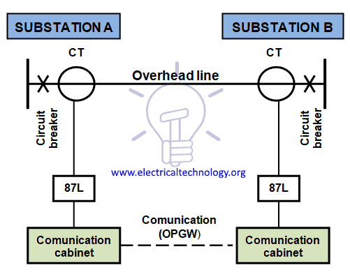
Figure 7 – Overhead line differential protection diagram
Another protective relaying system for HV transmission lines, based on differential protection principle that is nowadays in use even for long lines is phase comparison protection.
This system uses the principle of comparing the phase angle between the currents at the two ends of the protected line. During external faults the current entering the line is of the same relative phase angle as the current leaving the line, and the phase comparison relays at each terminal measure little or no phase angle difference.
The protection therefore stabilizes and no tripping occurs. For an internal fault the current will enter the line at both ends, and the phase comparison relays detect this phase angle difference. The relay then operates to clear the fault.
With phase comparison schemes starting relays are used to start the phase comparison process whenever a fault condition is detected. These starting relays must operate for both internal and external faults.
A reliable communication channel is required for phase comparison protection and fiber optic within OPGW cables have been used.
Figure 8 shows the the single line diagram of Merz Price voltage balance system for the protection of three-phase line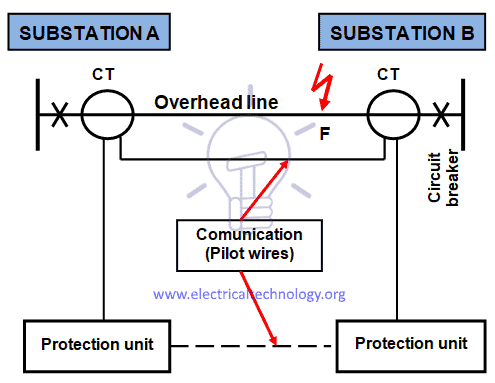
Figure 8 – Phase comparison protection diagram
Identical CT are placed in each phase at both ends of the line. The pair of CT in each end is connected in series association with a relay in such a way that under normal conditions, their secondary voltages are equal and in opposition, i.e., they balance each other.
Under healthy conditions, current entering the line at one-end is equal to that leaving it at the other end.
Therefore equal and opposite voltages are induced in the secondaries of the CT at the two ends of the line. The result is that no current flows through the relays.
When a fault occurs at point F on the line as shown in Figure 8 it will cause a greater current to flow through CT1 than through CT2.
Consequently, their secondary voltages become unequal and circulating current flows through the pilot wires and relays. The circuit breakers at both ends of the line will trip out and the faulty line will be isolated.
Distance protection
A distance relay measures the impedance of a line using the voltage and the current applied to the relay.
When a fault occurs on a line, the current rises significantly and the voltage collapses significantly.
Since the impedance of a transmission line is proportional to its length, for distance measurement it is appropriate to use a relay capable of measuring the impedance of a line up to a predetermined point (the reach point).
The distance relay (also known as impedance relay) determines the impedance by the equation Z = U/I (Ohm law).
Such a relay is designed to operate only for faults occurring between the relay location and the selected reach point, thus giving discrimination for faults that may occur in different line sections.
The apparent impedance so calculated is compared with the reach point impedance.
If the measured impedance is less than the reach point impedance, it is assumed that a fault exists on the line between the relay and the reach point.
If the impedance is within the reach setting of the relay, it will operate.
Distance protections are installed at both ends of the line and a communication is established between them, as shown in Figure 9.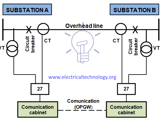
Figure 9 – Overhead line distance protection diagram
Distance relay performance is defined in terms of reach accuracy and operating time.
Reach accuracy is a comparison of the actual ohmic reach of the relay under practical conditions with the relay setting value in ohms and particularly depends on the level of voltage presented to the relay under fault conditions.
Impedance measuring techniques employed in particular relay designs also have an impact.
Operating times can vary with fault current, with fault position relative to the relay setting, and with the point on the voltage wave at which the fault occurs.
Depending on the measuring techniques employed in a particular relay design, measuring signal transient errors, such as those produced by Capacitor VT (CVT) or saturating CT, can also adversely delay relay operation for faults close to the reach point.
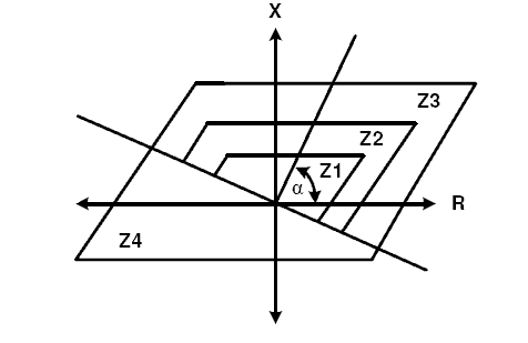
Characteristics of distance relays – protection shape – are defined as a graphic function of the resistance (R) and the impedance (X) of the line – R/X or admittance diagram.
Typical shapes are circular (mho characteristic) and quadrilateral, which are represented in Figures 10 and 11.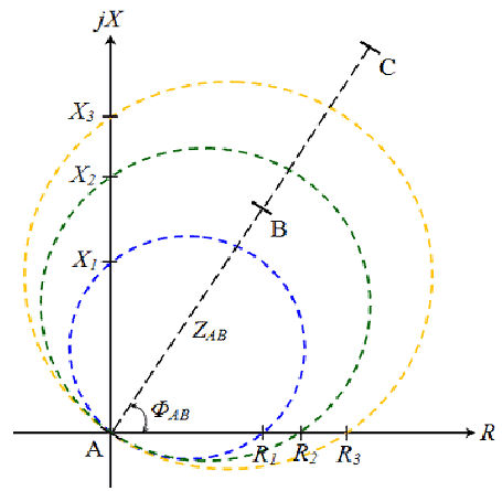
Figure 10 – Mho characteristic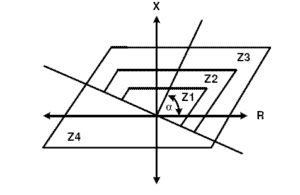
Figure 11 – Quadrilateral characteristic
The mho impedance element is generally known as such because its characteristic is a straight line on an admittance diagram.
Polygonal impedance characteristics are highly flexible in terms of fault impedance coverage for both phase and earth faults and for this reason, nowadays most distance relays offer this form of characteristic.
Distance relays may have up to five zones, some set to measure in the reverse direction (used as bus bar backup protection). To each zone corresponds an actuation time of the relay.
Distance relays are used in both sides of the line and each one of them sees the fault on different periods of time, depending of the distant of the faulty point (F) to each end of the line.
Considering an overhead line connecting Substations A and B, F will be seen first by the distance relay installed in the substation closer to F and the respective circuit breaker will trip first than the circuit breaker placed at the other substation.
To avoid that short-circuit fault continue to be feed by the other side of the line until the respective distance protection will actuate a communication link between protection relays, usually by optic fiber within OPGW cables, is required to simultaneous trip both circuit breaker.
It is not practical to set an impedance relay to measure exactly the impedance of the line up to the breaker at the remote end. This is because of errors and inaccuracies in such things as CT, VT, relays, calculation of line impedance, etc.
Because of this we set the relay to measure, or reach, some impedance less than the full length of the line (setting zone 1 of up to 85% may be safe and the 15-20% safety margin ensures that there is no risk of the zone 1 protection over-reaching the protected line due to those errors and inaccuracies; otherwise there would be a loss of discrimination with fast operating protection on the following line section).
Careful selection of the reach settings and tripping times for the various zones of measurement enables correct co-ordination between distance relays on a power system.
Reclosing
As analysed in Section 4.2 most of faults on overhead lines are asymmetric and transient.
The auto-reclose is performed through a relay (auto-recloser relay) initiated by the protection devices of the overhead line, like the one shown in Figure 12.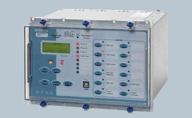
Figure 12 – Auto-recloser relay
There are various reasons for reclosing a line. It is imperative to have input and guidance from planning and operational groups to determine the appropriate reclosing practices for a particular Utility and Region. The following are some of the major considerations for transmission level reclosing:
- System stability.
- System security.
- Continuity of service.
The most important parameters of an auto-reclose scheme are:
- Dead time
- Reclaim time
- Single or multi-trip
These parameters are influenced by:
- Type of protection
- Type of switchgear
- Possible stability problems
- Effects on the various types of consumer loads
Reclosing can be either unsupervised high speed or time-delayed, supervised by voltage/synchronization elements. The decision as to which to apply must weigh the benefit and consequences of each to determine the acceptability of the risk in the particular application.
Reclosing on non-critical lines, as previously determined by the planning groups, may vary, and depending on protection philosophy and equipment applied.
Practices vary among utilities; reclosing practices also vary depending on voltage levels and the type of line considered.
Some companies auto-reclose for all faults and only block on loss of communications. Some utilities reclose if the speed of clearing is fast enough, independent of the fault configuration.
System stability is a determining factor on whether high speed auto-reclose is attempted.
The problems involved are dependent on whether the transmission system is weak or strong.
With a weak system, loss of a transmission link may lead quickly to an excessive phase angle across the circuit breaker used for re-closure, thus preventing a successful re-closure.
In a relatively strong system, the rate of change of phase angle will be slow, so that delayed auto-reclose can be successfully applied.
This includes concerns with reclosing too slowly and concerns that the system will enter instability if reclosed back onto a faulted line.
In situations where reclosing onto a faulted line does not impact the stability of the system, multi-trip reclose attempts may be possible. In this case, the restoration of the line is required more for load continuity to the customers.
In Europe is usual to use auto-recloser schemes only in HV networks, although in some countries, like the United States and Brazil, these schemes are also used in MV networks.
The most common type of power system fault is the flashover of insulators on overhead transmission lines, due to lightning.
The number of faults per year is proportional to the length, and is approximately inversely proportional to the voltage level.
Indicative figures of faults are:
- ≥ 500 kV overhead lines – 9 faults per year per 100 km.
- 150-400 kV overhead lines – 5 faults per year per 100 km.
- 60-138 kV overhead lines – 7 faults per year per 100 km.
For overhead lines up to 49.5 kV the figures are proportionally higher.
Table 1 shows the statistics of success of auto-reclosing faults clearance:
Table 1 – Statistic success of faults clearance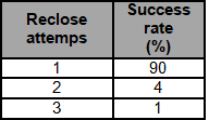
Cables Feeder Protection
Common Types of Faults and Causes
Common failure modes and faults of cables are:
Electrically induced failures
These involve lightning, switching surges, and partial discharges.
Partial discharges may be caused by poor insulation system design or by manufacturing defects.
Mechanically induced failures
A mechanically induced failure can occur during installation due to use of excessive pulling tension and/or exceeding minimum bending radii.
Cable can also be damaged during construction when earth moving equipment can dig into the cable or cable duct banks such as in submarine cables.
Repeated bending and twisting during installation or in service can result in irreversible straining of conductor wires.
Thermally induced failures
Thermal degradation causes the insulation of the cable to lose its physical properties and they are due to overloading beyond its design capability for extended periods and/or excessive ambient temperature conditions.
Metallic (semiconducting) shield damage
This failure mode describes where the shield ceases to perform its function.
In order for the shield to perform its function, its volume resistivity must always remain sufficiently low. However, when metallic shield is damaged or corroded its volume resistivity is impacted by temperature.
At higher temperatures, the volume resistivity of the metallic shield increases significantly (due to peak loads, unbalance currents, or circulating currents) giving rise to high voltage gradients at sharp metal edges that will lead to corona effect / discharge and arcing damage (from outside in).
Corona and arcing will lead to eventual cable insulation failure.
Poor Metallic Shield Contact
This is the case where metallic shield is insulated from the semiconducting tape shield because of poor contact, what can be caused by a layer of corrosion or scale buildup on the metallic shield.
Such a condition will give rise to a potential difference between the semiconducting shield and the metallic shield that will cause arcing between the two shields.
This will lead to arcing damage from the outside into semiconducting shield and insulation and eventual cable failure, being more severe if there are multiple areas of poor contact or breaks between the two shield systems.
Failures in most cases occur at the end-terminations or joints (where the factory-manufactured insulation gets disturbed).
Most specific causes of power cable failures are the following:
- Phase-to-earth short-circuit
- Phase-to-phase short-circuit
- Reduced insulation resistance
- Reduced dielectric strength
- Excessive partial discharge
Some of the major causes for cable failures are:
- Ageing
- Corrosion of sheath
- Electrical puncture
- Fire and lightning surges
- Heating of cables
- Mechanical failures
- Moisture in the insulation
- Wrong selection or application
Differential Protection
The ideal way of protecting any piece of power system equipment is to compare the current entering that piece of equipment, with the current leaving it.
Under normal healthy conditions the two are equal. If the two currents are not equal, then a fault must exist.
This is done through differential protection (87) that was discussed at Section 4 (Overhead Lines Protection) and that will be also discussed at Section 6 (Transformer Protection).
It is not economic or practical to provide a communication channel between the ends of a feeder to enable the currents entering and leaving the feeder to be compared.
For this reason this type of protection is not commonly used on LV and MV cable feeders and is used by some electric transmission companies in HV cables, mostly for voltages above 123 kV.
In this situation differential protection is used as main protection and overcurrent protection is used as back-up protection.
Overcurrent Protection for Cables
To define the type of overcurrent protections for cable feeders is necessary to look first at the network configuration.
MV distribution networks may have several types of configurations:
- Radial
- Ringed type
- Double-end feed with NO point
A combination of types above referred is used, and the most common configurations are radial and double-end feed with NO point.
LV distribution networks are usually radial.
MV and LV internal and private networks of plants and buildings are commonly radial, but in large plants a double-end feed with NO point may be observed in MV networks.
LV cable feeders may be protected against overcurrents by fuses (a common solution for distribution networks in Europe and North America) or by thermal magnetic devices within circuit breakers.
MV cable feeders, namely in public distribution networks in Europe and North America, may be protected by fuses against overcurrents.
With radial feeders and double-end feed with NO point there is only one possible point of supply, and the flow of fault current is in one direction only. Overcurrent protection can therefore be used to provide adequate protection.
Common relays used for this protection are instantaneous phase overcurrent (50), instantaneous earth overcurrent (50N), time delay phase overcurrent (51) and time delay earth overcurrent (51N).
The current entering the feeder at the circuit breaker is measured by means of a CT, as shown in Figure 13.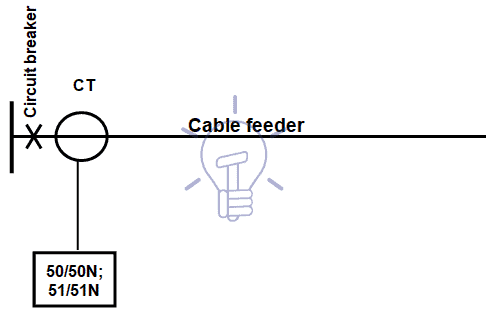
Figure 13 – Overcurrent protection wiring diagram
Let us consider the situation of a cable feeder between stations A and B, being B located downstream of A.
The overcurrent protection at the supply end of the feeder at station A must operate for all faults on the feeder, but should not operate for faults beyond station B.
If we first consider an instantaneous overcurrent relay, then setting is determined by the magnitude of the fault current at the end of the feeder at station B that is the lower fault current on the cable.
Ideally the relay will be set for that fault current and it should not operate for any fault beyond station B.
However, in practice it is not possible to be so precise for the following reasons:
- It is not possible for the relay to differentiate between faults which are very close to, but which is on each side the Bus ‘B’, since the difference in the currents would be extremely small.
- Inaccuracies in CT and relays, and the effects of distortion of the current waveform under transient conditions produce errors in the response of the protection scheme.
- The magnitude of the fault current cannot be accurately established since all of the parameters may not be known, and the source impedance of the power system changes as generators are put in and out of service.
One solution to solve this problem is to set the instantaneous overcurrent relay to overreach the remote terminal and introduce a definite time delay in tripping the circuit breaker.
This time delay will allow the overcurrent relays at the remote station to operate to clear faults beyond bus B before the time delayed tripping can take place at the supply station A.
This type of time delay has the major disadvantage that all faults will be slow cleared even very close-in faults, which have the highest magnitude of fault current.
This time-delayed clearing of high fault currents is usually unacceptable, and the most common feeder protection scheme, which overcomes the problem, utilizes an inverse time overcurrent relay (51) in conjunction with the instantaneous overcurrent relay (50).
In order to ensure that the instantaneous overcurrent relay will not unnecessarily operate for faults at the remote station, (which should be cleared by the overcurrent protection or fuses at that station) then it must be set to protect only part of the feeder. A safe maximum for most types of relay is 80% of the feeder length.
The limit is determined by the characteristics of the relay used, and the length of the feeder. If the feeder is long a high percentage of the line can be protected; but with short lines it may be less; and with very short lines it may not be possible to apply instantaneous overcurrent protection.
This type of protection is known as High-Set Instantaneous (HS) overcurrent protection.
With such a relay set to detect faults on 80% of the feeder, the remaining 20% is left unprotected. This is, of course, not acceptable. To provide protection for the last 20% of the feeder a time-graded, or inverse definite minimum time relay can be used.
The inverse definite minimum time” relay has a characteristic “time-current” curve as shown in Figure 14.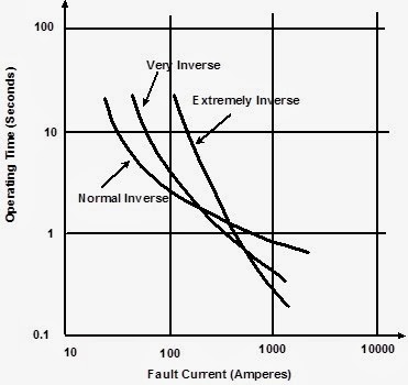
Figure 14 – Characteristic “time-current” curve of inverse definite minimum time relay
Using this characteristic “time-curve” it shall be defined the co-ordination of upstream and downstream protections, a topic that was discussed at Section 3.3.
Now let us look at a typical utility feeder which supplies customer transformers at many different points along its length.
The same High-Set Instantaneous Overcurrent and Inverse Timed Overcurrent relays are used, and the HS relay must be set such that it does not operate for faults beyond the first tap.
HS relay will therefore be set to operate for faults up to 80% of the distance to the first tap.
The criteria used for setting the Inverse-Timed Overcurrent relay are:
- The relay must not operate for the maximum load current that will be carried by the feeder.
- The relay setting must be sensitive enough for the relay to operate and clear faults at the very end of the feeder.
- The relay operating characteristic must be set to coordinate with other protection devices, such as fuses, ‘downstream’ from the supply station.
This type of protection scheme will provide adequate protection for feeders.
However, there are some disadvantages with this arrangement, particularly on long overhead feeders. The main disadvantage is that most faults will be slow in clearing because the inverse time overcurrent relay must operate. This slow fault clearing is usually disturbing to customers on the affected feeder.
The criteria used for setting the High-set Instantaneous Overcurrent Relay are:
- The relay must be set to operate for faults up to, but not beyond, the first tap from the feeder.
- In practice, the relay is set to operate for faults up to 80% of the distance to the first tap.
- This provides high-speed clearance for the high level faults close to the supply
In networks with a ringed type configuration fault current can flow in either direction, and the feeder overcurrent protection at the supply station may require directional supervision on those feeders that in normal situation have only one current direction.
A directional relay – directional phase overcurrent (67) and directional earth overcurrent (67N) – must be used when the phase-to-earth short-circuit current (I”K1) is lower than the maximum residual capacitive current[4] (ICM). in the same situation – ICM ≥ I”K1.
Phase-to-earth short-circuit current depends on the neutral grounding system of the network.
Directional overcurrent protection comprises overcurrent relay and power directional relay.
The power directional relay is not used to measure power, but is arranged to respond to the direction of power flow.
The protection relay is connected to CT and VT, as shown in Figure 16.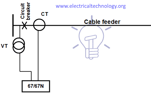
Figure 16 – Directional overcurrent protection wiring diagram
Transformer Protection
Transformer Faults
Transformers faults may occur in the dielectric (oil, gas[5] or resins/varnishes), due to ageing, contamination with air, gas formation and lack of pressure and level.
Windings may also be subjected to faults, such as overheating and insulation breakdown.
Overheating may be caused by overloads above the permissible overloads specified by the manufacturers, according to IEC Standards (60354 for oil-filled transformers and 60905 for dry type transformers), and external faults, such as short-circuits on installations downstream. Most of these faults may be limited by proper maintenance of a transformer.
Overheating may cause a breakdown of the insulation of the windings.
Transformer Built-on Protections
Transformers are provided with internal (built-on) protections for oil pressure, level and temperature, dielectric failure (formation of gas), winding temperature and on-load tap changer.
According to the construction type of transformers the following protections must be provided:
Oil-filled transformers with conservator
- Buccholz relay for dielectric failure (2 steps: alarm and trip)
- Oil pressure and level switches (2 steps: alarm and trip)
- Thermostat for oil temperature (2 steps: alarm and trip)
- On-load tap changer protection (2 steps: alarm and trip)
Buccholz relay has multiple methods to detect a failing transformer.
- On a slow accumulation of gas, due perhaps to slight overload, gas produced by decomposition of insulating oil accumulates in the top of the relay and forces the oil level down. A float switch in the relay is used to initiate an alarm signal. Depending on design, a second float may also serve to detect slow oil leaks.
- If an arc forms, gas accumulation is rapid, and oil flows rapidly into the conservator. This flow of oil operates a switch attached to a vane located in the path of the moving oil.
Buchholz relays have a test port to allow the accumulated gas to be withdrawn for testing. Flammable gas found in the relay indicates some internal fault such as overheating or arcing, whereas air found in the relay may only indicate low oil level or a leak.
Oil-filled sealed transformers
- Gas detection and oil level, pressure and temperature in one single equipment (DGPT2 – Detection of Gas, Pressure and Temperature) with 2 levels (alarm and trip)
Dry type transformers
- Temperature of windings with 2 levels (alarm and trip) – resistance temperature detector PT 100 (platinium) or PTC (Positive Temperature Coefficient), that is a thermistor (semi conductive material sensitive to temperature).
These protections have a direct action on the tripping coils of the circuit breakers.
Differential Protection
Transformers and autotransformers for voltages above 49.5 kV and MV transformers with rated power above 3-4 MVA have usually as main protection a differential protection (87T), for winding faults – short-circuits between turns of a winding or between windings that correspond to phase-to-phase or three-phase type short-circuits.
If there is no earthing / grounding connection at the transformer location point, this protection can also be used to protect against earth faults.
If the earth fault current is limited by impedance, it is generally not possible to set the current threshold to a value less than the limiting current.
Differential protection is connected to CT (Current Transformers) at both sides of the transformer (primary and secondary).
- Problem relating to the transformation ratio and the coupling method
The primary and secondary currents have different amplitudes owing to the transformation ratio and different phases depending on the coupling method (delta-star transformer makes a phase displacement of 30°). Therefore, the current values measured must be readjusted so that the signals compared are equal during normal operation.
This is done using matching auxiliary transformers whose role is to balance the amplitudes and phases.
When one side of the transformer is star-connected with an earthed neutral, the matching transformers on this side are delta-connected, so that residual currents that would be detected upon occurrence of an earth fault outside the transformer are cleared.
Figure 16 shows an example of the connection of the differential protection, using matching auxiliary transformers.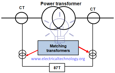
Figure 16 – Transformer differential protection diagram
Nowadays, with electronic and microprocessed protection units, this compensation is done through software.
Function of the protection is based on the transformation ratio “n” that can be expressed by the equation:
n = (U1 / U2) = (I2 / I1)
(U1: primary voltage; U2: secondary voltage; I1: primary current; I2: secondary current).
The above relation is a consequence of the equation of the rated power (S) of the transformer:
S = √3 x U1 x I1 = √3 x U2 x I2
- Problem relating to the transformer inrush current
Transformer switching causes a very high transient current (from 8 to 15 In), which only flows through the primary winding and lasts several tenths of a second.
It is thus detected by the protection as a differential current and it lasts far longer than the protection operating time (30 ms). Detection based only on the difference between the transformer primary and secondary currents would cause the protection to be activated. Therefore, the protection must be able to distinguish between a differential current due to a fault and a differential inrush current.
Experience has shown that the inrush current wave contains at least 20% of second harmonic components, while this percentage is never higher than 5% upon occurrence of an overcurrent due to a fault inside the transformer.
The protection must therefore simply be locked when the percentage of second harmonic component in relation to the fundamental harmonic component (50 Hz or 60 Hz) is higher than 15%, i.e., “I2 / I1 > 15%”.
- Problem relating to the magnetizing current upon occurrence of an overvoltage of external origin
Magnetizing current, or exciting current, is the current that flows through the primary winding of a power transformer when no loads are connected to the secondary winding; this current establishes the magnetic field in the core and furnishes energy for the no-load power losses in the core. It is responsible for “iron losses”.
The magnetizing current constitutes a difference between the transformer primary and secondary currents. It is therefore detected as a fault current by the differential protection even though it is not due to a fault.
In normal operating conditions, this magnetizing current is very low and does not reach the protection operating threshold.
However, when an overvoltage occurs outside the transformer, the magnetic material saturates (in general the transformers are dimensioned to be able to operate at saturation limit for the nominal supply voltage), and the magnetizing current value greatly increases. The protection operating threshold can therefore be reached.
Experience has shown that the magnetizing current due to the magnetic saturation has a high rate of fifth harmonic components.
Transformer differential protection therefore requires fairly complex functions as it must be able to measure second and fifth harmonic current or, in order to avoid measuring fifth harmonic currents, it must be able to detect overvoltages of external origin.
The characteristics of transformer differential protection are related to the transformer specifications:
- Transformation ratio
- Vector group
- Inrush current
- Permanent magnetizing current
Overload Protection Protection in Transformer
The basic criterion for transformer loading is the temperature of the hottest spot of the solid insulation (hot-spot). It must not exceed the prescribed value, in order to avoid insulation faults, since loading capability of power transformers is limited mainly by winding temperature.
The temperature of solid insulation is the main factor of transformer ageing.
With temperature and time, the cellulose insulation undergoes a depolymerization process. As the cellulose chain gets shorter, mechanical properties of paper such as tensile strength and elasticity degrade. Eventually the paper becomes brittle and is not capable of withstanding short circuit forces and even normal vibrations that are part of transformer life. This situation characterizes the end of life of the solid insulation and since it is not reversible, it also defines the transformer end of life.
Transformer overloads can occur during contingency conditions that are the product of one, two, or various system elements being isolated from the power the system. They can also occur when transformers are already at 80%-90% of their full nameplate rating and extra capacity is needed, especially during hot summers.
Traditionally, inverse-time overcurrent relays have been used for overload protection, but a difficulty is that transformers are usually outdoors where ambient temperature affects their loadability, and hence the optimum pickup settings of such relays.
However, for liquid-immersed power transformers, the temperature of the winding hot-spot is the important factor in the long-term life of the transformer.
The insulating oil temperature is dependent on the winding temperature, and is used to indicate the operating conditions of the transformer. Many numerical transformer protection relays available today include protection functions that operate on insulating oil temperatures, calculated loss-of-life due to high oil temperature, and predicted oil temperatures due to load.
These types of functions are not routinely applied, but modern utility operating practices try to maximize the utilization of power transformers, which may increase the occurrence of over-temperature conditions, and transformer ageing. Over-temperature conditions and accelerated aging are adverse system events that must be identified and protected against.
Most common function provided for thermal protection of power transformers is the thermal overload (ANSI/IEEE/IEC 49) function.
The thermal capacity used is calculated according to a mathematical model which takes into account:
- Current rms[6] values
- Ambient temperature
- Negative sequence current.
The protection gives a trip order when the heat rise E, calculated according to the measurement of an equivalent current Ieq, is greater than the set point Es.
The protection tripping time is set by the time constant T.
The thermal overload protection function may be used to protect equipment with two operating rates, for example transformers with two ventilation modes, with or without forced ventilation (ONAN/ONAF – oil natural-air natural/oil natural-air forced).
Overcurrent Protection in Transforemer
MV transformers with rated power up to 2.5-3 MVA are usually only protected against overcurrents using overcurrent relays – instantaneous phase overcurrent (50), instantaneous earth overcurrent (50N), time delay phase overcurrent (51) and time delay earth overcurrent (51N).
This set of protections is used on HV transformers and MV transformers with rated power above 3-4 MVA as a back-up protection, in addition to the differential protection.
In some installations and networks, MV/BT transformers with rated power up to 630-1250 kVA may be protected against overcurrents by fuses associated to switch-disconnectors, as shown in the Fiigure 17.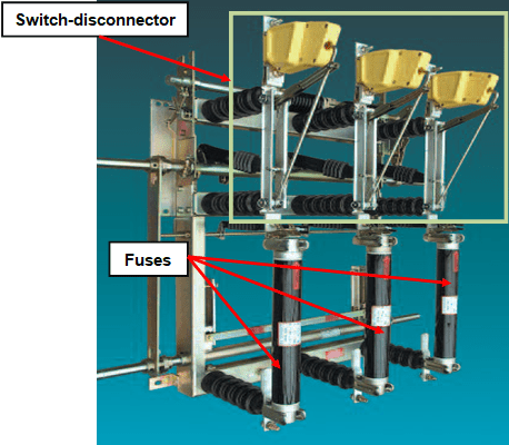
Figure 17 – MV switch-disconnector associated with fuses
For the protection of power transformers manufacturers provide tables to choose the rated current of a fuse, taking into account the rated voltage and power, as shown in Table 2, according to IEC Standards.
Tables vary from manufacturer to manufacturer, according to the standards used, being recommended to use the table provided by the selected manufacturer.
Table 2 – Rated current of fuses for power transformers protection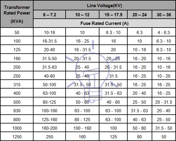
Restricted Earth Fault Protection
Restricted earth fault protection (64G/64REF) is used as a complement or to replace differential protection for phase-to-earth winding faults; figure 18 shows the diagram of this protection.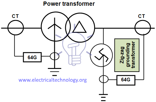
Figure 18 – Transformer restricted earth fault protection diagram
In a transformer with a star connection winding, if an external fault happens, the current through the faulty phase is equal to the current through the neutral conductor; hence, the current through the protection is zero, what makes this protection not sensible to external faults to the transformer.
If loads are unbalanced the sum of the three currents through is not zero and a there is a current in the neutral conductor, but the sum of all currents (phases and neutral) is zero, and so this protection is not sensible to unbalanced loads.
Transformers Fire Protection System
We have already discussed about it in detail in our previous post “Transformers Fire Protection System – Causes, Types & Requirements“.
Motor Protection
Common Motor Failures and Faults
It is important to know and to understand motor failures and faults to define the most suitable protection devices for each case. You also must know about important terms related to motor control and protection.
Being non-static machines motors are subjected to electrical and mechanical stress.
Motor failures come in three basic types: electrical, mechanical and mechanical that progresses into electrical.
Common motor failure and faults are:
- Bearing failure
- Insulation breakdown
- Locked rotor
- Overheating
- Overloads (electrical and mechanical)
- Phase imbalance and any voltage imbalance will lead to an even higher current unbalance.
- Running in reverse
- Shaft misalignment
- Vibration
Overheating can occur from undersizing the motor, insufficient cooling at low speed when using variable speed drives (VSD), changes to the load on the motor such as jammed equipment and hot ambient conditions.
Insulation breakdown, leading to burnt windings, imply short-circuit either within the motor or within the power supply circuit for the motor, and may be caused by overheating, overloads and overvoltages.
About 80% of electrical motor failures are a result of winding damage in the motor stator and bearing faults.
Bearing failure on motors can be an indication of the incorrect bearings for the application.
A motor mounted vertically needs different bearings then a motor horizontally mounted. A motor driving a large or multi-belt drive will require bearings that handle big radial loads. A motor bolted to a distorted base plate will twist.
Bearings are usually small compared to other major motor components, making them particularly vulnerable to damage and wear; some studies blame more than half of all motor failures on bearing malfunction, most of which result from too little or too much lubrication. Another significant cause of bearing failure is misalignment.
Shaft misalignment will destroy bearings well before their full working life. The motor shaft must be directly in-line with the shaft it is driving what can only be achieved using precision alignment techniques such as laser.
Other problems that may occur with motors are:
- Water and dust ingress into the stator coils or the terminal housing leading to short-circuits
- Soft foot motor feet bolted down out of level
- Wrong motor mounting or housing type
- Electrical or mechanical unbalance
Noise indicates motor problems but ordinarily does not cause damage. Noise, however, is usually accompanied by vibration.
Vibration can cause damage in several ways. It tends to shake windings loose and mechanically damages insulation by cracking, flaking or abrading the material. Embrittlement of lead wires from excessive movement and brush sparking at commutators or current collector rings also results from vibration.
Finally, vibration can speed bearing failure by causing balls to “brinnell” sleeve bearings to be pounded out of shape or the housings to loosen in the shells.
Whenever noise or vibrations are found in an operating motor, the source should be quickly isolated and corrected.
What seems to be an obvious source of the noise or vibration may be a symptom of a hidden problem. Therefore, a thorough investigation is often required.
Noise and vibrations can be caused by a misaligned motor shaft or can be transmitted to the motor from the driven machine or power transmission system. They can also be the result of either electrical or mechanical unbalance in the motor.
Electrical unbalance occurs when the magnetic attraction between stator and rotor is uneven around the periphery of the motor. This causes the shaft to deflect as it rotates creating a mechanical unbalance. Electrical unbalance usually indicates an electrical failure such as an open stator or rotor winding, an open bar or ring in squirrel cage motors or shorted field coils in synchronous motors. An uneven air gap, usually from badly worn sleeve bearings, also produces electrical unbalance.
The chief causes of mechanical unbalance include a distorted mounting, bent shaft, poorly balanced rotor, loose parts on the rotor or bad bearings. Noise can also come from the fan hitting the frame, shroud, or foreign objects inside the shroud. If the bearings are bad, as indicated by excessive bearing noise, it is necessary to determine why the bearings failed.
Another problem motors can face is a long start time. If a motor is subjected to many successive starts, the rotor windings or rotor bars can be heated up to a point where the electrical connections between the rotor bars and the end rings are damaged.
Motor Protection Devices
No matter what rated voltage and size motors have they are protected against overcurrents (short-circuit) and overloads.
Small and medium size LV motors are usually only protected against overloads and short-circuits and large LV motors and MV motors have also other protections.
Overload and overcurrent protections must be designed to be insensitive to in-rush currents at starting time, to avoid untimely power interruption.
For LV motors the protection against overcurrents and short-circuits can be performed by fuses, associated to switch-disconnectors or instantaneous trip circuit breakers that respond to immediate (almost instantaneous) values of current from a short circuit, ground fault, or locked rotor current.
Inverse time circuit breakers have both thermal and instantaneous trip features and are preset to trip at standardized levels.
This is the most common type of circuit breaker used in the building trades for residential, commercial, and heavy construction.
The thermal action of this circuit breaker responds to heat. If a motor’s ventilation inlets and outlets are not adequate to dissipate heat from the windings of the motor, the heat will be detected by the thermal action of the circuit breaker.
If short-circuit should occur, the magnetic action of the circuit breaker will detect the instantaneous values of current and trip the circuit breaker.
Fuses usually are not suitable for the protection against overloads, because if sized to provide overload protection, they would blow when the motor starts due to high motor inrush current, although they can be used as an overload back-up protection.
Protection with fuses presents the risk of single-phasing damage to the motor when only one fuse blows unless single-phase protection is provided; this subject will be discussed later on this chapter.
Large size LV motors and MV motors are protected against short-circuits (phase-to-phase and phase-to-earth) by overcurrent relays (50; 50N; 51; 51N) connected to CT.
The protection against overloads is normally assured by thermal overload relay. This relay can be of the following types:
Bi-metallic strip
A thermal overload protection will accommodate the brief high starting current of a motor while accurately protecting it from a running current overload. The heater coil and the action of the bi-metallic strip introduce a time delay that affords the motor time to start and settle into normal running current without the thermal overload tripping. Thermal overloads protections can be manually or automatically resettable depending on their application and have an adjuster that allows them to be accurately set to the motor run current.
Ambient temperature in which a starter and motor is located must be considered when selecting bi-metallic strip relays because a high ambient temperature reduces overload trip time.
Reduced overload trip time can lead to nuisance tripping if a motor is located in a cooler ambient temperature than the starter and leads to motor burnout when the motor is located in a hotter ambient temperature than the starter.
Most thermal overload devices are rated for use at a maximum temperature of 40 ºC, and a derating of the relay may be required.
Most relays are adjustable over a range from 85% to 115% of their value.
Some models are available with ambient compensation. An ambient compensated devices trip point is not affected by ambient temperature and performs consistently at the same value of current.
This type of relays is commonly used on low and medium size LV motors.
Standards and manufacturers’ data usually show recommended regulation set-point of this type of relays in accordance with rated power of the motor; same tables also show recommended rated currents of fuses (aM or gG type – see Section 2.4) and instantaneous circuit breakers that are associated to the relays for overcurrent protection, as shown in Table 3.
Table 3 – Rated fuses current for motor protection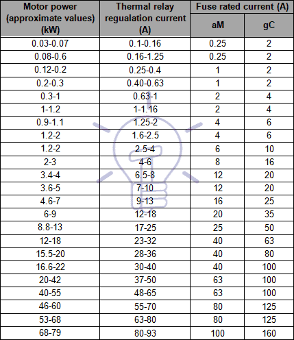
Electronic Digital Overload Relays
This type of protection is used for large LV motors and HV motors, and contains a microprocessor. These devices may model the heating of the motor windings by monitoring the motor current and they can also include metering and communication functions.
Common protection of large LV motors and MV motors is usually done by the following protection devices:
- Overload protection: 49
- Instantaneous phase overcurrent: 50
- Instantaneous earth overcurrent: 50N/50G
- Time delay phase overcurrent: 51
- Time delay earth overcurrent: 51N/51G
In some situations it is not recommended to protect motors against overloads; that is the case of fire fighting water pumps and smoke exhaust fans.
Very large LV motors and MV motors are expensive, and it is usually wise to provide more comprehensive protection schemes. Such schemes include:
- Bearing temperature monitors and protection (38)
- Differential protection (87M)
- Incomplete start sequence / long start time protection (66)
- Negative phase sequence (phase reversal protection)
- Overheating protection
- Phase unbalance or phase failure protection (47)
- Stall or locked rotor protection
- Under and over voltage protection (27 and 59, respectively)
- Vibration monitors and protection (39)
- Winding temperature monitors and protection devices
Differential protection is often provided for medium and large size motors with supply voltages of greater than about 4 kV, and electrically operated (shunt trip) circuit breakers. The differential protection provides high speed direction and clearance of faults on the motor stator windings.
Where the power supply system is solidly grounded the differential protection will detect both phase-to-phase and phase-to-ground faults.
With differential protection the current at each end of each winding is compared to determine when a fault condition exists.
This function requires two sets of CT, one at beginning of the motor feeder, and the other at the star point.
The differential protection function can only be used if both sides of each stator phase are brought out of the motor for external connection such that the phase current going into and out of each phase can be measured. The differential element subtracts the current coming out of each phase from the current going into each phase and compares the result or difference with the differential pickup level.
If this difference is equal to or greater than the pickup level a trip will occur.
Figure 19 shows an example of this protection.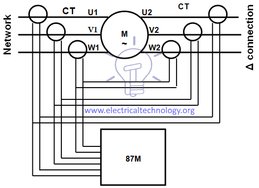
Figure 19 – Motor differential protection
Using six CT in a summing configuration, during motor starting the values from the two CT on each phase may not be equal as the CT are not perfectly identical and asymmetrical currents may cause the CT on each phase to have different outputs.
To prevent nuisance tripping in this configuration, the differential level may have to be set less sensitive, or the differential time delay may have to be extended to ride through the problem period during motor starting.
The running differential delay can then be fine tuned to an application such that it responds very fast and is sensitive to low differential current levels.
Windings overheating protection is usually done with Resistance Temperature Detectors (RTD) and thermistor and automatic shut down devices can be installed. Attaching a separate booster fan to aid the motor fan solves the overheating problem when a VSD is used to control the motor speed.
Incomplete start sequence / long start time causes rotor overheating.
As it is not possible to physically measure the heat of the rotor on squirrel-cage motors is necessary to determine the heat by measuring the current the rotor is drawing through the stator to excite the rotor. A thermal replica of the rotor is established using an I2t curve.
The restart inhibit will block the user from starting the motor if the relay determined that the rotor reached a temperature that will damage the rotor should a start be attempted. The relay will thus only allow a restart if the rotor has a sufficient thermal reserve to start.
Bearing protection is usually performed by RTD and thermistor to monitor the temperature.
Vibration protection uses sensors/accelerometers that are typically placed at key locations on the motor and bearings.
Since the bearings are the load carrying part of the mechanical drive train, accelerometers should be placed on the input and output
Figure 20 shows an example of vibration sensors and recommended locations.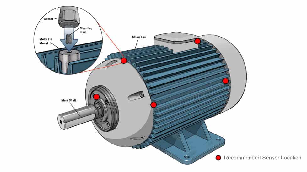
Figure 20 – Motor vibration sensors
Nowadays IED (see Section 2.1) that group all required protection functions are commonly used for large LV motors and MV motors.
Generator Protection
Common Generator Faults
Generator faults are usually classified into internal and external faults; internal faults are due to problems within the generator components and external faults are due to abnormal operating conditions and faults on external networks.
Faults on prime mover[7] and associated systems will not be discussed, since they are usually defined at mechanical design stage of the equipment.
However they must be integrated within generator protections for tripping purposes.
Internal faults may be either electrical or mechanical
1. Stator faults
- Windings overheating
- Windings phase-to-phase fault
- Windings phase-to-earth fault
- Inter-turn fault
2. Rotor faults
- Earth fault
- Winding short-circuit (wound rotor)
- Overheating
3. Loss of field / excitation[8]
4. Generator Out-of-Step
5. Motor operation
6. Bearings overheating and lack of pressure of lubrication oil
7. Vibration
Stator windings overheating may be caused by permanent overloads and phase-to-phase and earth faults are due to insulation breakdown.
Rotor winding short-circuit leads to an increase of excitation current and a decrease of excitation voltage.
Rotor overheating is a consequence of unbalanced currents at the stator, due to:
- Single-pole trip
- Stator winding fault
- Negative phase sequence
Negative phase sequence and unbalanced currents in the stator currents and produces an armature flux rotating in the opposite direction to the rotor, inducing eddy currents in the rotor mass.
These eddy currents, which are at twice the system frequency (50Hz or 60 Hz), will produce local overheating at the periphery of the rotor that may cause weakness in the rotor retaining wedges and rings.
When a generator loses excitation (or field), reactive power flows from the power system into the generator. The generator then loses synchronism and runs as an induction generator, above synchronous speed.
Above synchronous speed the rotor will start to oscillate in an attempt to lock into synchronism, resulting in overheating and other damage. As long as the system is stable, reactive power (MVAr) will flow into the generator and the machine will continue to put out active power (MW).
Generators motor operation may occur when the steam or water supply to the turbine fails and generators draws power from the electrical system.
In steam turbines the steam acts as a coolant, maintaining the blades at a constant temperature. Failure of the steam supply can cause overheating of the blades. On some machines the temperature rise is very low, and motoring can be tolerated for a considerable time.
Hydraulic turbine will have cavitation (formation and then immediate implosion of cavities in liquid – small liquid-free zones (“bubbles“) – that are the consequence of forces acting upon the liquid).
It usually occurs when a liquid is subjected to rapid changes of pressure that cause the formation of cavities where the pressure is relatively low.
Cavitation is a significant cause of wear. When entering high pressure areas, cavitation bubbles that implode on a metal surface cause cyclic stress through repeated implosion, resulting in surface fatigue of the metal.
External power system faults and abnormal operating conditions are:
- External short-circuit faults
- Non-synchronized connection of generator
- Out-of-step (pole slipping or loss of synch)
- Overloads
- Overspeed
- Phase unbalance and negative phase sequence
- Under and over frequency
- Under and over voltages
An uncleared or slow clearing fault on the network system can cause generators to start slipping poles, or go “out-of-step” with the rest of the system.
Such a condition is undesirable because harmful mechanical stresses are exerted on the shaft, and the severe power swings have a disturbing effect on the power system voltages.
Loose of synchronism may be caused by an external short-circuit, switching off of an important inductive load or by a fault at the excitation system.
Overspeed is the consequence of a suddenly switching off of the total load or an important reduction of load.
Generator Protection Devices
Generators are the most expensive pieces of equipment on power systems.
Reliable protective relaying schemes are therefore required to detect and clear generator faults quickly to minimize damage and reduce repair time to a minimum.
Protection against stator windings phase-to-phase faults is performed through a differential relay, which principle was previously discussed at other sections. This protection device is not able to detect winding inter-turn faults.
When such a type of fault occurs phase voltage decreases and a zero-sequence voltage appears; this voltage is detected by a voltage relay (ANSI/IEEE/IEC code 60) connected to VT.
Stator ground faults protection depends of stator grounding.
For resistance grounding system an overcurrent relay connected to a “ring type” CT within the neutral connection or a voltage relay at resistance terminals may be used.
Under normal healthy conditions no current flows through the resistance and the voltage at the terminals is equal to zero.
For grounding through a transformer a voltage relay checking the voltage at the resistance connected to the secondary of the transformer is used.
Under normal healthy conditions the grounding transformer develops no secondary voltage, and no voltage is applied to the relay. When a stator ground fault occurs, a voltage is developed across the grounding transformer secondary terminals, and the voltage relay operates.
Figure 21 shows typical connection for stator differential and earth-fault protection.
Figure 21 – Differential and stator earth-fault protections
Wound rotor winding short-circuit faults are protected by overcurrent relays.
The rotor windings may be damaged by earth faults.
The rotor or field winding on large thermal generators is ungrounded, thus a single ground fault produces no fault current.
A single ground fault, however, raises the potential of the whole field and exciter system, and the extra voltages induced by opening the field breaker, or the main generator breaker, particularly under fault conditions, may increase stress to the ground in the field, when the stator transients induce an extra voltage in the field windings. This extra voltage may cause a second fault on the field winding.
A second fault to ground may cause local heating of the iron which could distort the rotor, causing dangerous unbalance.
The protection against rotor earth-faults may be provided by a relay that controls the insulation of the rotor by applying an auxiliary AC voltage to the rotor or a voltage relay in series association with a high resistance (linear and non-linear resistors combination is the common method used nowadays) connected across the rotor circuit, the center point of which is connected to ground through the coil of a sensitive relay (ANSI/IEEE/IEC code 64).
Nowadays modern technique calls for the use combining linear and non-linear resistors.
Figure 22 shows an example of rotor earth fault protection.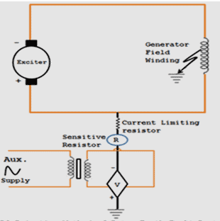
Figure 22 – Rotor earth-fault protection
Loss of field protection uses a relay that detects the change in reactive power flow. A typical loss of excitation protection scheme uses an Offset Mho (impedance) relay to measure the generator load impedance.
The Offset Mho impedance relay is a single phase relay, and is supplied from the generator CT and VT. The loss of field relay will operate if the value of the load impedance falls within the operating characteristic of the relay.
A timing relay is included to initiate tripping of the machine if the leading reactive power condition persists for 1 s (typical).
To prevent core saturation due to overexcitation during run up and shutdown an overexcitation protection (ANSI/IEEE/IEC code 59) is used.
Overexcitation can be explained by the following equation:
B = V / f
Where B is the magnetic flux density or magnetic induction or core flux (unit: tesla – T), V is the applied voltage (unit: volt – V) and f the frequency (unit: hetz – Hz).
For the core flux to remain below the saturation point, the generator voltage may only be increased as the frequency (or speed) is increased.
If the excitation is increased too rapidly, then this overexcitation condition must be detected, and the field breaker tripped.
Overexcitation protection schemes use Volts per Hertz relays.
These relays have a linear characteristic, and will operate if the voltage divided by the frequency exceeds the set value.
Stator windings and bearings overheating protection is usually performed by RTD and thermistor to monitor the temperature.
Stator phase unbalance protection commonly uses a time-inverse overcurrent relay, which is set in accordance with the maximum time rotor can withstand this overheating.
The function of generator negative phase sequence protection is to protect the machine against the overheating effects, namely at the rotor, which occur as a result of unbalance of the stator phase currents.
This protection uses a relay that compares the current at two phases through CT, as show in Figure 23.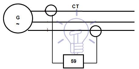
Figure 23 – Negative phase sequence protection
Protections are set in accordance with the maximum time rotor can withstand this overheating and time is defined by the equation K = I2t (based in Joule law).
Typical curves for this condition is shown depend on the prime mover and are indicated by the manufacturer.
Reverse Power protection (ANSI/IEEE/IEC code 32) uses a power directional relay to monitor the generator load; the relay is supplied from the generator CT and VT as shown in Figure 24 and will operate when any negative power flow is detected.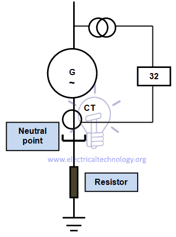
Figure 24 – Reverse power protection
Out-of-Step protection detects a condition caused by power system disturbances, rather than generator faults. The protection detects the condition when the generator slips its first pole, and causes the generator breakers to trip.
The turbine is not tripped enabling the machine to be re-synchronized after the system disturbance is cleared.
This protection can be considered complementary to Loss of Excitation protection.
The out-of-step condition occurs with the generator at full field and the loss of synchronism due to underexcitation occurs when the generator has no field.
Out-of-Step protection uses three impedance measuring relays. These relays are supplied by the generator CT and VT and measure the generator load impedance, detecting a power swing condition if the three relays operate in the correct sequence and will initiate tripping of HV circuit breakers.
For external short-circuit faults overcurrent relays are used (50; 50N; 51; 51N).
Under and over frequency protection (ANSI/IEEE/IEC code 81) detects also system disturbances, rather than generator faults. A major power system break-up can result in either an excess or insufficient generating power for the remaining connected load.
In the first case, overfrequency, with possible overvoltage results because of the reduced load demand. Operation in this mode will not produce overheating unless rated power and approximately 105% rated voltage are exceeded.
The generator controls should be promptly adjusted to match the generator output to the load demand.
With insufficient generation for the connected load, underfrequency is the result of heavy load demand.
The drop in voltage causes the voltage regulator to increase excitation. The result is that overheating can occur both in the rotor and the stator. At the same time, more power is being demanded, with the generator less able to supply it at the decaying frequency.
Automatic or manual transmission system load shedding should ideally adjust the load to match the connected generation before a total power system collapse occurs.
Over and under voltage relays (ANSI/IEEE/IEC codes 59 and 27) are used to control the voltage.
Phase supplementary start protection is provided to detect a condition where a fault exists when the generator is being run up to speed. Generators must not, of course, be started-up into a load or into a fault condition.
To prevent this, a scheme of protection is used that switches into service low-set overcurrent relays ONLY if the frequency is below 52 Hz on 60 Hz power systems and 42 Hz on 50 Hz systems.
Nowadays IED (see Section 2.1) that group all required protection functions are commonly used for generator protection.
Miscellaneous Protection
Voltage and Frequency Protection
Load fluctuation and switching and power plants failures may cause variations on voltage and frequency of the network that can exceed the accepted limits of equipments and networks operation.
This situation can lead to damages on equipments and partial or total black-out in the network.
To avoid or to minimize this situation under and over voltage (codes 27 and 59, respectively) and frequency (codes 81U and 81O, respectively) protections shall be used.
Bus Bar Protection
In HV substations is common to install a bus bar protection relay, being the most used the differential protection (87B).
This relay is connected to all CT of the substation to evaluate the sum of incoming and outgoing currents, as shown in figure 25.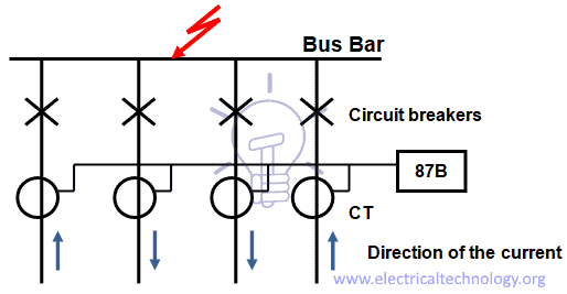
Figure 25 – Bus bar differential protection diagram
The operating principle of this protection is based on Kirchhof laws – current law.
The bus protection CT must be located on the feeder side of the breakers. If the bus protection CT are located on the bus side of the breaker, then a protection blind spot exists.
By using High Impedance relays in differential protection the system can be designed to be more tolerant of a saturated CT.
A non-linear resistor is connected across the relay terminals to limit the voltage across the differential relay to a safe value during fault conditions.
High impedance relays are used extensively in modern differential protection for high voltage buses.
The advantage of using High Impedance relays in bus differential protections is that they can be designed to remain stable (not operate) for external faults, when any one of the CT has saturated.
For an external fault, the worst case is with one CT completely saturated and the other CT not saturated. The resulting differential current will cause the maximum voltage to occur across the differential relay. A relay setting (in volts) is chosen, with sufficient margin, to ensure that the differential protection does not operate for this external fault condition.
The resistance of the CT secondary windings and cabling must be known, and is used in the relay setting calculations.
For internal faults the high impedance of the differential relay forces much of the resulting differential current through the CT exciting impedances. The resulting voltage developed across the relay is essentially the open-circuit voltage of the CT, and will be well above the voltage setting of the relay. A non-linear resistor or varistor is connected across the relay terminals to limit the voltage to a safe value during fault conditions.
When a bus fault is detected, all of the circuit breakers on that bus are tripped. Bus faults are almost always permanent, rather than transient faults.
There must therefore be no auto-reclosing of breakers after a bus fault. Bus protections will often cancel the auto-reclose on any breaker which may have been initiated by another protection.
Many substations use bus bar arrangements such as double bus bar, as shown in the Figure 26, where feeders can be switched from one bus to another by means of isolating switches.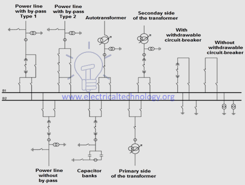
Figure 26 – Double bus bar arrangement
This complicates the bus protection somewhat, because the CT secondary circuits must be switched, by means of the isolator auxiliary switches, to correspond with the appropriate bus.
It is usual to have one zone of protection for each section of the bus. These are known as discriminating zones.
There is also another zone of differential protection for the entire substation, which is known as the check zone.
For tripping of a bus to take place with this arrangement it is necessary for both a discriminating zone relay and the check zone relay to operate.
Breaker Failure Protection
In HV substations is common the use of breaker failure protection (50BF), if a breaker fails to be triggered by a tripping order, as detected by the non-extinction of the fault current, this back-up protection sends a tripping command to the upstream or adjacent breakers.
The breaker failure protection function is activated by a 0/1 binary signal received from the overcurrent protection functions (50/51, 50N/51N, 46, 67N, 67). It checks for the disappearance of current during the time interval specified by the time delay T.
It may also be taken into account the position of the circuit breaker, read on the logic inputs to determine the actual opening of the breaker. Wiring a volt-free closed circuit breaker position contact on the breaker closed equation editor input can ensure that the protection is effective in the following situations:
- When 50BF is activated by protection function 50N/51N (set point Is0 < 0.2 In), detection of the 50BF current set point can possibly be not operational.
- When trip circuit supervision (TCS) is used, the closed circuit breaker contact is short-circuited.
Automatic activation of this protection function requires the use of the program logic circuit breaker control function. A specific input may also be used to activate the protection from the equation editor. That option is useful for adding special cases of activation (e.g. tripping by an external protection unit).
The time-delayed output of the protection unit should be assigned to a logic output via the control matrix.
The starting and stopping of the time delay T counter are conditioned by the presence of a current above the set point (I > Is).
Weak End Infeed
Weak end infeed protection is a complement to the distance protection that is used if the value of fault current in the overhead line is lower than the set-point regulation of the distance protection.
Capacitor Banks Protection
When it comes to Power factor, Each phase of a capacitor bank is formed by groups of capacitors in series association for power factor improvement. The 3 phases are then connected in star, being the neutral point isolated or grounded, according to the operation of the network, as shown in Figure 27.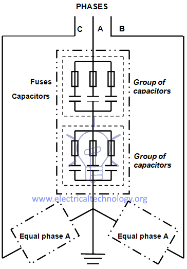
Figure 27 – Diagram of a capacitor bank
Common capacitor banks faults are:
- Capacitors short-circuit or fault in the connection cables.
- Short-circuit between the units and the metallic structure of racks or switchboards (phase-to-earth fault).
- Overloads caused by network harmonics.
- Dielectric breakdown due to network overvoltages or lightning.
When a group of capacitors fail and the neutral is grounded the bank will be imbalanced and a current will circulate in the neutral.
Each capacitor or group of capacitors is usually protected by fuses, which are already installed by the manufacturer.
Fuses must have an I2t characteristic that will not cause the fuse to blow with the inrush current resulting from the connection of the capacitor bank.
Common protection devices of capacitor banks are:
- Instantaneous phase overcurrent (50)
- Instantaneous earth overcurrent (50N/50G)
- Time delay phase overcurrent (51)
- Time delay earth overcurrent (51N/51G)
- Over voltage protection (49)
[1] HV: High Voltage (V ≥ 60 kV); MV: Medium Voltage (1 kV < V < 60 kV); LV: Low Voltage (V ≤ 1 kV).
[2] IEC: International Electrotecnical Comission.
[3] IEEE: Institute of Electrical and Electronics Engineers. ANSI: American National Standards Institute.
[4] Residual capacitive current in the case of phase-to-earth fault (IC) is calculated by the equation IC = 3XcU, where Xc is the capacitive reactance of the cable and U the phase-to-phase voltage of the network.
[5] In this article Gas Insulated Transformers (GIT) are not analasyzed.
[6] rms: root mean square.
[7] Prime mover is the component that is used to drive the generator and may be combustion engines (the case of diesel generator sets), gas turbines, steam turbines, wind turbines and hydraulic turbines.
[8] The field in an AC generator consists of coils of conductors within the generator that receive a voltage from a source (called excitation) and produce a magnetic flux.
The magnetic flux in the field cuts the armature to produce a voltage. This voltage is ultimately the output voltage of the generator.

About the Author: Manuel Bolotinha
-Licentiate Degree in Electrical Engineering – Energy and Power Systems (1974 – Instituto Superior Técnico/University of Lisbon)
– Master Degree in Electrical and Computers Engineering (2017 – Faculdade de Ciências e Tecnologia/Nova University of Lisbon)
– Senior Consultant in Substations and Power Systems; Professional Instructor
The post All About Electrical Protection Systems, Devices And Units appeared first on Electrical Technology.
March 26, 2018 at 06:28AM by Department of EEE, ADBU: https://ift.tt/2AyIRVT
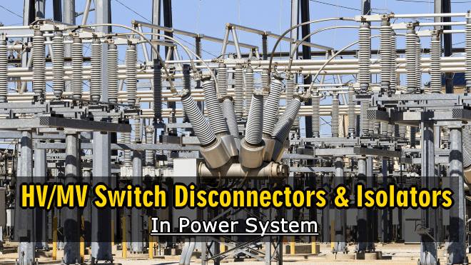
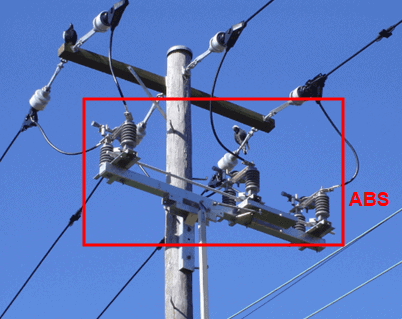
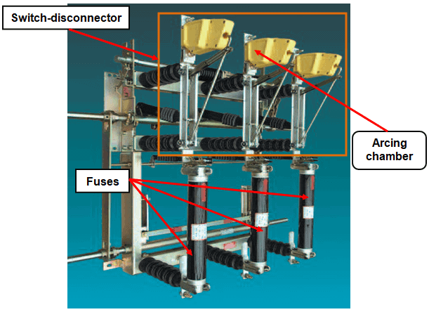
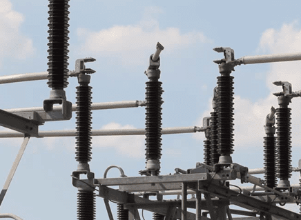 Figure 3 – Centre horizontal rotating isolator
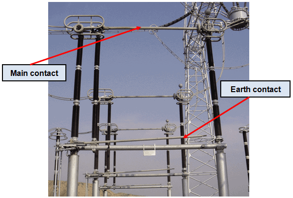 Figure 4 – Double vertical rotating isolator
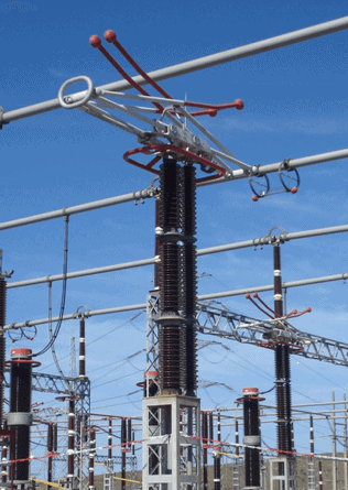 Figure 5 – Pantograph isolator
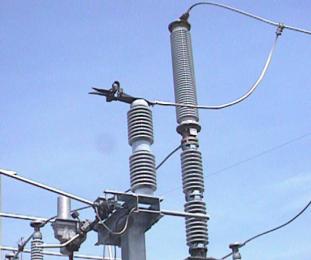 Figure 6 – Earthing isolator