What are Harmonics and How to Filter and Eliminate it.
(Manuel Bolotinha)
Introduction to Harmonics
The quality of electrical power supply is an important issue both for utility companies and users, but that quality may affected by electromagnetic disturbances.
Among these disturbances it must be highlighted harmonics that happens in all voltage levels and whose study, calculation of acceptable values and correction methods are defined in IEC[1] Standard 61000-2-4: Electromagnetic compatibility (EMC)[2] – Environment – Compatibility levels in industrial plants for low-frequency conducted disturbances.

What are Harmonics?
Alternators produce alternated voltages (V) and currents (I) with a sinusoidal wave form and a frequency (f) of 50 Hz or 60 Hz (this frequency, the first harmonic, is usually designated by industrial frequency or fundamental), what can be observed in Figure 1.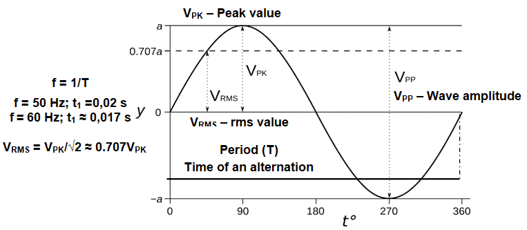
Figure 1 – Sinusoidal alternated voltage
However, due to some equipments characteristics, which are installed in the network, voltages and/or currents with different frequencies, odd integral multiples of industrial frequency, may be induced in the network, the harmonics, i. e.: 3th harmonic – 150 Hz or 180 Hz; 5th harmonic – 250 Hz or 300 Hz; 7th harmonic – 350 Hz or 420 Hz; etc.
We can say then that harmonics are continuous (steady-state) disturbances or distortions on the electrical network and are a completely different subject or problem from line spikes, surges, sags, impulses, etc., which are categorized as transient disturbances.
Figure 2 shows examples of 1st harmonic, 3th harmonic and 5th harmonic.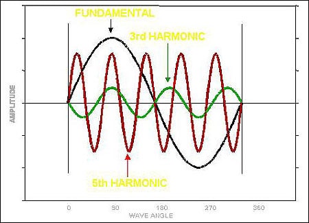
Figure 2 – Fundamental, 3th harmonic and 5th harmonic waves
The presence of harmonics gives origin to a distorted wave of voltage (or current) that may be observed in Figure 3, taking into account that all complex waveforms can be resolved into a series of sinusoidal waves of various frequencies, therefore any complex waveform is the sum of a number of harmonics of lesser or greater value.
Fourier series[3] expresses the instantaneous value of that sum – u(t) – by the equation: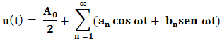 Where:
- t is the time [s]
- ω = 2πf [s-1]
- T is the period [s]
- f0 is the fundamental frequency [Hz]
- s(t) is a periodic function integrable in the interval [0, T]
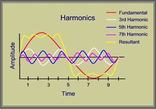
Figure 3 – Harmonic distortion
Usually 3th harmonic is the most harmful, but in certain conditions, 5th and 7th harmonics cannot be overlooked.
Harmonic Distortion
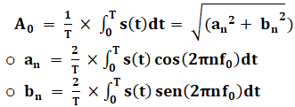
According to IEC Standard 61000-2-4 harmonic distortion is characterized by the parameter THD – Total Harmonic Distortion – calculated by the equation: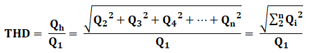
Where Q1 represents the rms value of the voltage or of the current at industrial frequency and Qi the harmonic wave of order “i” (2nd harmonic – i=2; 3th harmonic i=3; etc.) of the voltage or of the current.
The same IEC Standard defines also the following parameters:
- TDC (Total Harmonic Content), which rms value is calculated by the equation:
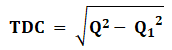
Where Q1 represents the rms value of the voltage or of the current at industrial frequency and Q the rms value of the voltage or of the current.
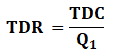
- TDR (Total Harmonic Ratio) – relation between the rms value of TDC and the rms value of the voltage or of the current at industrial frequency (Q1), which is calculated by the equation:
Usually calculations are made for the voltage, considering minimum three-phase short-circuit power (S”K) of the network and maximum values (in Ω) of short-circuit impedance in the points where THD is calculated (ZK; RK; XK[4]); a specific software is required to do these calculations.
The above referred IEC Standard defines 3 classes for electromagnetic environment[5]:
- Class 1: This class applies to protected supplies and has compatibility levels lower than those on public networks. It relates to the use of equipment very sensitive to disturbances in the power supply, for instance electrical instrumentation in laboratories, some automation and protection equipment, some computers, etc.
- Class 2: This class applies generally to PCC[6] and to IPC[7] in the environments of industrial and other non-public power supplies. The compatibility levels of this class are generally identical to those of public networks. Therefore, components designed for supply from public networks may be used in this class of industrial environment.
- Class 3: This class applies only to IPC in industrial environments. It has higher compatibility levels than those of class 2 for some disturbance phenomena. For instance, this class should be considered when any of the following conditions are met: a major part of the load is fed through converters; welding machines are present; large motors are frequently started; loads vary rapidly.
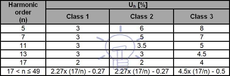
Harmonic compatibility levels[8] (Uh [%]) for odd frequencies multiples of 3 are indicated in Table 1and for odd frequencies not multiples of 3 are indicated in Table 2.
Table 1 – Levels of harmonic compatibility for odd frequencies multiples of 3
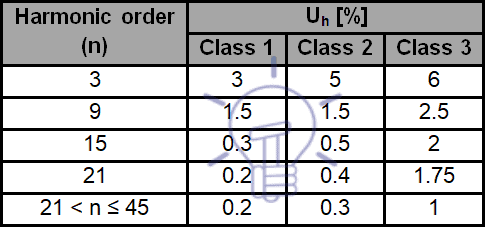
Table 2 – Levels of harmonic compatibility for odd frequencies multiples of 3
Compatibility levels of THD for each of the classes are:
- Class 1 – 5%.
- Class 2 – 8%.
- Class 3 – 10%.
Sources and Effects of Harmonics
Harmonics are a permanent source of problems in electrical equipments and systems.
The following types of loads (non-linear loads [9]) are the main sources of harmonics:
- Power electronic equipment (example: rectifiers – namely those used in electrical traction systems – and static converters).
- Arcing equipment (example: arc furnaces, AC or DC, arcing welding machines).
- Saturable devices (example: off-load current wave absorbed by a transformer with an insufficiently large power rating).
To minimize harmonics generation rectifier units are preferably six-pulse and these type of units for electrical traction systems typically generate current harmonics of 5th, 7th, 17th and 19th order, resulting from diodes unbalancing and from network impedance.
Although of a lower magnitude, under normal working conditions of equipments and of network, it must be taken into account the risk of resonance for those frequencies.
Switching operations of capacitor banks and power transformers with a permanent overload are also an important harmonics source.
Power transformers for voltages above 60 kV with star-star connection (Yy) are equally a harmonic source. To compensate those harmonics, the referred power transformers must have a tertiary winding, delta connected.
Apart from the distortion of voltage wave, harmonics are an origin of erroneous operation of control and protection systems, due to electromagnetic interferences, increase skin effect [10], cause mechanical oscillation and vibrations of electrical machines, namely power transformers and rotating machines, decrease power factor (cos Φ), conduce to premature ageing of insulation materials, leading to the lost of their dielectric characteristics, origin overheating and losses increasing, namely power transformers and cables, and decrease useful life of equipments.
Harmonics, which are the cause of voltage wave distortion, circulating in non-linear loads, like motors, when subjected to a variable magnetic flux, induce circulating currents (Foucault currents) in conducting materials, what decrease torque.
In unbalanced systems, harmonics may cause a neutral current higher than the vectorial sum of phase currents at fundamental frequency, leading to an overload in the neutral conductor.
Skin effect increases conductors’ resistance and therefore voltage drop and losses by Joule effect. This issue is particularly sensitive in overhead lines with a voltage above 150 kV and a length of 800 km and above. Common solution to solve this problem is to use DC overhead lines, in which skin effect does not exists.
Mechanical oscillation and vibrations of rotating electrical machines may origin shaft misalignment and destruction of stator, rotor and bearings.
Losses increase in power transformers, happens in iron losses, due to Foucault currents and hysteresis[11], which are proportional to the frequency and in copper losses, due to skin effect.
Harmonics Compensation & Types of Filters
When capacitor banks are used for power factor correction, a significant harmonics component flows into the capacitor bank; in these situations is necessary to temporarily switch-off the capacitor bank to allow an accurate location of harmonics sources.
In such an installation it is crucial to verify if there is any risk of harmonic resonance caused by the specific capacitor bank harmonics. This is the first step to define the correct solution for harmonic compensation.
Once confirmed the existence of harmonics and that THD value exceeds the limit defined by IEC Standard 61000-2-4 and/or established by the utility company it is mandatory proceed to harmonic compensation; the solution to be implemented depends on the installation characteristics.
The simplest solution, used in low voltage (V ≤ 1 kV) installations, is the use of copper coils (see Figure 4) that act as high frequency filter, limit the starting current of rectifiers and restrain mutual interference.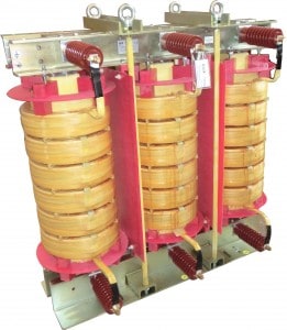
Figure 4 – Reactance for harmonic compensation
The inductance (L) of each phase is calculated by the equation: Where:
- ΔVL is the internal voltage drop of the reactance [%]
- Vn is phase-to-phase voltage of the network [V]
- fn is the industrial frequency of the network [Hz]
- In is the current [A]
In networks and installations with a strong electrical pollution (higher harmonics level), where Gh/Sn > 60% (Gh is the apparent power of all non-linear loads responsible for harmonics production and Sn is the apparent power of all upstream transformers connected to the same bus bar where loads are connected) is recommended to install harmonics filters, like the one shown in Figure 5).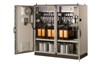
Figure 5 – Harmonics filter
Harmonics compensation may be centralized, with harmonic filters connected in the main incoming switchboard, or de-centralized or local, installing the harmonic filters close to the equipments that are the main sources of harmonics. Both solutions are shown in Figure 6.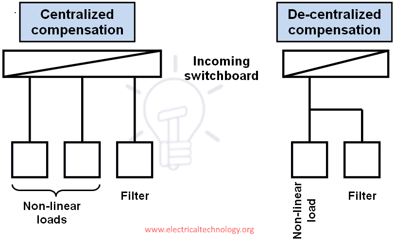
Figure 6 – Location of harmonic filters
Harmonic filters are classified into three categories:
Passive filters
These are constituted by LC series association circuits, tuned for each one of the frequencies that they are designed to compensate, usually 5th, 7th and 11th harmonics. Their main characteristics are:
- There is no limit to harmonic to current to be eliminated.
- They perform power factor correction.
- They risk amplifying harmonics when there are network modifications.
- There is an overload risk, caused by external electromagnetic pollution.
Active filters
These are constituted by electronic and micro-processed units, controlling harmonics within a range between 2nd to 50th orders; for each range of frequency it is generated a current, which has a phase shift of 180° and the same value of the harmonic current to be compensated.
This type of filters is well adapted to modifications of the network, of the loads and of the harmonic range, being particularly suitable for de-centralized or local compensation.
Hybrid filters
These are a combination of active and passive filters, controlling harmonics within a range between 2nd to 25th orders, doing also power factor correction.
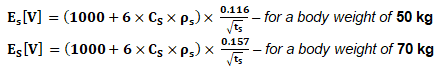
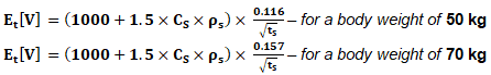
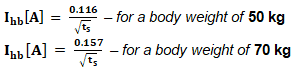
Good to know:
Good to know:
[1] IEC: International Electrotechnical Comission.
[2] Electromagnetic compatibility is defined as the capability of electrical equipments to worker properly in a “electromagnetic environment” without introducing any type of electromagnetic disturbances in other equipments and systems that may exist in that environment.
[3] Fourier series are converging trigonometric series used to represent the sum of sinusoidal functions.
[4] If the values of RK e XK of the network it is usual to consider, as an approximation, RK/XK = 0.1 and the equation
ZK = √(RK2+XK2).
[5] The definition of the classes is a transcription of IEC Standard 61000-2-4.
[6] PCC: Point on a public power supply network, electrically nearest to a particular load, at which other loads are, or could be, connected.
[7] IPC: Point on a network inside a system or an installation, electrically nearest to a particular load, at which other loads are, or could be, connected.
[8] Compatibility level defines the specified electromagnetic disturbance level used as a reference level in a specified environment for coordination in the setting of emission and immunity limits.
[9] A load is said non-linear if its impedance vary with applied voltage.
[10] Skin effect is a phenomenon that can be characterized by the repulsion of electromagnetic current lines, which consequence is a tendency for AC current to flow only at the surface of conductors.
[11] Hysteresis is the by which, when magnetic field is applied to a ferromagnetic material, as the core of the transformers, the material stays permanently magnetized, even if the magnetic field is not present.

About the Author: Manuel Bolotinha
-Licentiate Degree in Electrical Engineering – Energy and Power Systems (1974 – Instituto Superior Técnico/University of Lisbon)
– Master Degree in Electrical and Computers Engineering (2017 – Faculdade de Ciências e Tecnologia/Nova University of Lisbon)
– Senior Consultant in Substations and Power Systems; Professional Instructor
The post Introduction to Harmonics – Effect of Harmonics on Power System appeared first on Electrical Technology.
February 24, 2018 at 01:45AM by Department of EEE, ADBU: http://ift.tt/2AyIRVT


 Where: