Emergency Planning for Safety & Protection in Industries & Installations
Emergency Planning in Industries & Installations
Emergency Plan
Health and Safety organization and national regulations call for industrial and commercial companies and installations to have an emergency plan, to minimize the consequences of technological and natural hazards and to prevent possible disaster.
In addition an emergency plan promotes safety awareness and shows the organization’s commitment to the safety of workers.
The lack of an emergency plan could lead to severe losses such as multiple casualties and possible financial collapse of the organization.
Technological Hazards
Areas where flammables, explosives, or chemicals are used or stored should be considered as the most likely place for a technological hazard emergency to occur. Examples of these hazards are:
- Fire
- Explosion
- Building collapse
- Major structural failure
- Spills of flammable liquids
- Accidental release of toxic substances
- Exposure to ionizing radiation
- Loss of electrical power
- Loss of water supply
Natural Hazards
- Earthquakes
- Tornadoes
- Other severe wind storms,
- Snow or ice storms
- Severe extremes in temperature (cold or hot)
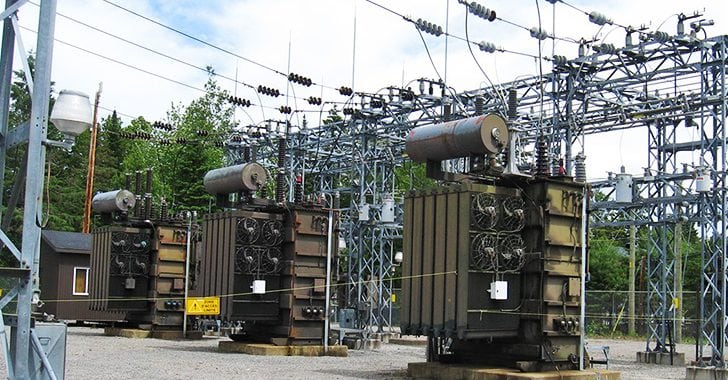
Related Post: Power Transformers Maintenance, Diagnostic & Monitoring
An emergency plan specifies procedures for handling sudden unexpected situations and the objectives of such a plan are to reduce the possible consequences of the emergency by:
- Preventing fatalities and injuries
- Reducing damage to buildings, stock, and equipment
- Accelerating the resumption of normal operations
- Decrease the potential impact to the environment, and to the community
The procedures to develop an emergency plan depend on:
- The degree of emergency
- The size of organization
- The capabilities of the organization in an emergency situation
- The immediacy of outside aid
- The physical layout
Emergency plans are subjected to a planning stage, several groups shall be asked to participate, such as joint occupational health and safety committee and municipal officials, and hazards must be identified and the impact of each of them must be itemized, such as:
- Sequential events (for example, fire after explosion)
- Evacuation
- Casualties
- Damage to plant infrastructure
- Loss of vital records/documents
- Damage to equipment
The events listed above will define the required actions and the location of resources needed.
- Related Post: Power Transformer Protection & Faults
Required Actions
- Declare emergency
- Sound the alert
- Evacuate danger zone
- Close main shutoffs
- Call for external aid
- Initiate rescue operations
- Attend to casualties
- Fire fighting
Resources Needed
- Medical supplies
- Auxiliary communication equipment
- Power generators
- Respirators
- Chemical and radiation detection equipment
- Mobile equipment
- Emergency protective clothing
- Firefighting equipment
- Ambulance
- Rescue equipment
- Trained personnel
Communication, training and periodic testing and revision will ensure adequate performance if the plan must be carried out.
An emergency plan must include the following items:
- All possible emergencies, consequences, required actions, written procedures, and the resources available
- Detailed lists of personnel including their home telephone numbers, their duties and responsibilities
- Floor plans
- Large scale maps showing the “meeting points”, evacuation routes, location of firefighting systems, alarm and panic buttons and service
Communications & Phone Numbers
When an accident occurs communication is vital to alert the internal teams in charge of security and external organizations that may be available to assist the fight against the hazardous occurrence and the rescue of personnel.
At strategic locations internal and external phone numbers of emergency teams and organizations must available.
Emergency phone numbers must include:
- National emergency number
- Fire departments
- Mobile rescue squads
- Ambulance services
- Police departments
- Telephone company
- Hospitals
- Utility companies
- Government agencies
Related Post: Primary and Secondary or Backup protection in a Power System
Panic Buttons
Panic buttons must be installed at strategic locations and are used as an emergency alarm to provide warning where someone is working and may need help or conditions reach an alarming state.
When a panic button is pressed an alarm will be sent and the alarm condition or status will continue until the panic button is manually reset.
Related Post: Cables Feeder Protection – Faults Types, Causes & Differential Protection
Electrical Fires & Fire Fighting
Classification of fires is important in order to define the firefighting methods to be used and the most appropriate extinguishing agent. The table below shows the most common classes of fires.
In Europe this classification is made in accordance with EN (European Standards) Standard 2:1992 and in America according to NFPA (National Fire Protection Association) standards.
There are four elements needed to start and sustain a fire and/or flame. These elements are:
- Reducing agent (fuel)
- Heat
- Self-sustained chemical chain reaction
- Oxidizing agent (oxygen)
In industry the most common causes for fire are electricity and chemical products, like gasoline and fuel oil.
Electrical fires are fires involving potentially energized electrical equipment. This sort of fire may be caused by short-circuiting machinery or overloaded electrical cables. These fires can be a severe hazard to firefighters using water or other conductive agents: Electricity may be conducted from the fire, through water, the firefighter’s body, and then earth. Electrical shocks have caused many firefighter deaths.
Electrical fire may be fought in the same way as an ordinary combustible fire, but water, foam, and other conductive agents are not to be used. While the fire is or possibly could be electrically energized, it can be fought with any extinguishing agent rated for electrical fire. Carbon dioxide (CO2) and dry chemical powder extinguishers such as ABC powder are especially suited to extinguishing this sort of fire.
However for power transformers is usual to use “pulverized water” to fight the fire.
Chemical fires are normally extinguished using sprinkler systems, CO2 and dry chemical power.
- Related Post: Overhead Lines Protection – Faults & Protection Devices
National Fire Protection Association (NFPA) Standards
NFPA standards are the most important standards in what concerns firefighting. The more relevant standards are listed below:
- NFPA 1 – Fire Code
- NFPA 10 – Standard for Portable Fire Extinguishers
- NFPA 11 – Standard for Low, Medium, and High-Expansion Foam
- NFPA 12 – Standard on Carbon Dioxide Extinguishing Systems
- NFPA 13 – Standard for the Installation of Sprinkler Systems
- NFPA 15 – Standard for Water Spray Fixed Systems for Fire Protection
- NFPA 17- Standard for Dry Chemical Extinguishing Systems
- NFPA 30 – Flammable and Combustible Liquids Code
- NFPA 901: Standard Classifications for Incident Reporting and Fire Protection Data
Related Read: Power Transformer Protection & Faults

The post Emergency Planning for Safety & Protection in Industries & Installations appeared first on Electrical Technology.
June 26, 2018 at 09:35PM by Department of EEE, ADBU: https://ift.tt/2AyIRVT
What is Fixture’s Beam Angle & Beam Diameter (Part-1)
Introduction:
- Lamps are available with multiple beam angle options hence Beam angle is an important factor in lighting design.
- The beam angle is the width of light that is emanated from the bulb and it is measured in degrees and can vary according to the different styles of bulbs.
- The beam angle of the Light is mainly depend ceiling height or distance of an object from the light source, and the lux level (brightness) which is required for a particular object or floor area.
Light Terminology
-
Lumens:
- Lumen is the total amount of light emitted by that lamp in all directions.
- The luminous flux (Lumen) is provided by lamp manufacturers and common lumen values are included on the lamp.

-
Lux:
- It is amount of illumination intensity in specified direction of specified area.
- Lumen is related to lux. one lux is one lumen per square meter.
- 1 lux = 1 lumen/m²
- Lux is simply the amount of lumens in a specified area.

- Lux is measured on a distance of 1 or 10 meters.
Difference between Lumen and Lux:
- The difference between the lumen and lux is that the lux takes into account the area over which the luminous flux (Lumen) is spread.
- A flux of 1000 lumens, concentrated into an area of 1 square meter lights with a luminance of 1000 lux.
- The same 1000 lumens, spread out over 10 square meters, produces a dimmer illuminance of only 100 lux.
- Mathematically, 1 lux = 1 lm/m2.
- Lumens are measured in all directions from the light source. This is not the best measurement to describe how bright a light is going to be on a specific area.
- To perfect describe How much lights going to on Specified area ,luminance lux or foot-candle are used.
- Lux changes according to beam angle and height
Difference between Beam Angle, Field Angle and Cut off Angle:
Beam Angle:
- The beam angle is the degree of widththat light emits from a light source.
- Beam Angle is the angle of the light between two points of 50% of Maximum intensity.
- It helpful in knowing how much “usable” light the fixture puts out in a fairly even field.
Field angle:
- It is the angle between the two directions opposed to each other over the beam axis for which the luminous intensity is 10% that of the maximum luminous intensity.
- In certain fields of applications the field angle was formerly called beam angle.
- This angle tells you how far the light reaches until it (basically) fades into the darkness.
Cut off Angle:
- This the angle which encompasses all forward light emitted by the directional lamp.

Relation between Beam Angle and Filed Angle:
- The Beam and Field Angles determine how a spot light lights the surrounding area.
- Normally, the field angle should be 180 degrees, because that creates a softer transition at the edge of the beam angle.
- If we change the default field angle to 180 to 75 this should give better results and it tighter angle, then over rider it.

Selecting Beam Angle for various Applications:
- Beam angle is an important factor in lighting design and Lamps are often available with multiple beam angle options.
- The beam angle of the Light we choose is determined initially by the ceiling height or distance of an object from the light source, and the lux level (brightness) that is required for a particular object or floor area.

-
Smaller beam angles (25° to 45° degrees):
- It will produce a more focused beam of higher intensity and are more suited to spot lighting in commercial or artistic applications.
- Buildings with very high ceilings of 3m or greater may also benefit from more focused beam angles.
-
Medium beam angle (40 degrees):
- This is a medium spread beam that offers a good combination of intensity and coverage.
-
Wider beam angles (60 degrees):
- Very popular for Down lights. A 60 degree beam can be used more effectively in larger rooms. Although the wider beam spread doesn’t provide more light, it does spread the light out further. If we need higher brightness, higher lumen output down lights will be required as a down lights for a good level of uniformity.
-
Larger beam angles (60° to 135° degrees):
- It will produce a broader beam suited for most residential applications or ambient lighting in commercial applications.
- They are also useful in lower ceiling applications (< 3m). Whereas a 45° beam spread may be more useful in higher ceiling applications or for corridor lighting.
- A bulb with a wide beam angle ensures to get a really clear, even light.
- The spread of light makes no dark areas in the room; and can allow you to use fewer bulbs.
-
Very Larger beam angles (120° degrees):
- LED light bulbs of 120° or greater are used in high light dispersion applications in place of traditional incandescent or CFL light bulbs or T5, T8 and T12 fluorescent tubes. While 60° to 90° LED light bulbs are more common halogen down light replacements.

|
Various Beam Angle as per Applications |
|||
| (MR Type) Flood Light | (PAR Type) Spot Light | Descriptions | Applications |
| <7° | <15° | Very Narrow Spot | Highlight a small statue or figure on display in a museum or in a jewelry store to make diamonds “pop.” |
| 5° to 15° | 15° to 30° | Narrow spot | Special or sale item or in landscape bullets illuminating a sign or garden feature. |
| 16° to 22° | 30° to 60° | spot | Used in stores to highlight a special or sale area or outdoors to illuminate an architectural feature. |
| 23° to 32° | 60° to 90° | Narrow flood | highlight a display table, while homes might use this bulb in recessed eyeball lights to illuminate a painting |
| 32° to 45° | 90° to 120° | flood | Pendant lights in coffee shops to recessed lights in living rooms. |
| 45° to 60° | 120° to 160° | Wide flood | Common in many general illumination applications from motion-sensing lights above garage doors to recessed cans in auditoriums and movie theaters. |
| >60° | >160° | Very wide flood | used to illuminate without highlighting any particular object or area. They’re good options for outdoor flood lighting and low-ceiling recessed lights. |
|
Ceiling Height and Beam angle |
|
| Ceiling Height | Beam Angle |
| 2.5 to 3.5 meters | 60° beam angle |
| 3.5 to 4.5 meters | 38° or 40° beam angle |
| 5 meters | 24° to 30° beam angle |
June 23, 2018 at 08:07PM by Department of EEE, ADBU: https://ift.tt/2AyIRVT
Measurements of bad impulsive noise in HV substation caused by partial discharge (PD) sources
The phenomenon of impulsive noise is generated by partial discharge (PD) sources in high voltage substations. A PD generates a current impulse, acoustic noise, visible and ultraviolet (UV) light and... Read more
The post Measurements of bad impulsive noise in HV substation caused by partial discharge (PD) sources appeared first on EEP - Electrical Engineering Portal.
View more at http://electrical-engineering-portal.com/impulsive-noise-measurements-hv-substation
Credit- Electrical Engineering Portal. Published by Department of EEE, ADBU: tinyurl.com/eee-adbu
Critical role of time synchronisation in IEC 61850 based digital protection systems

The needs and exact precision of time synchronization in IEC 61850 based digital protection systems have evolved. With new technologies and better distribution methods, most modern intelligent electronic devices (IEDs)... Read more
The post Critical role of time synchronisation in IEC 61850 based digital protection systems appeared first on EEP - Electrical Engineering Portal.
View more at http://electrical-engineering-portal.com/time-synchronisation-iec-61850-digital-protection-systems
Credit- Electrical Engineering Portal. Published by Department of EEE, ADBU: tinyurl.com/eee-adbu