How to do Lighting Design Calculation in a Building – Electrical Wiring Installation
In professional field proper lighting design is very important because an under lighting arrangement will decrease the efficiency of the task for which the lightings were designed and an over lighting arrangement will result in over expenditure of the company. On small scale this difference is not too much to worry about but in large buildings, plants, factories, etc it becomes very significant in today electrical wiring installations.
The simple and basic approach for calculating the lighting requirement is to divide the total light requirement of the room by light output (lumen) provided by a single lamp. Although this is the basic approach for an average household room, but it’s not practically accurate.
In practical there are several other parameters which are necessary to be considered in the calculation because nothings Ideal. For example the luminaries lumen output won’t be the same throughout the entire life span, dust deposition on lamps will also reduce their output over time which means cleanliness is also an important parameter. A bright painted room reflects more light than a dark coloured room so they both have different lighting requirements.
So it is important to first understand few basic terms about lighting design before beginning the calculations.
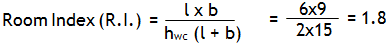
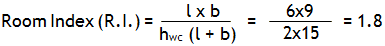
Room Index- It is based on shape and size of the room. It describes the ratios of the room’s length, width and height. It’s usually between 0.75 to 5.
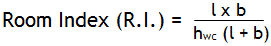
Where “l ” is the length of the room,
“w” is the width of the room and,
hwc is height between work plane i.e. Bench to Ceiling
This formula for Room Index is applicable only when room length is less than 4 times the width.
Maintenance Factor:
It is ratio of the lamp lumen output after a particular interval of time as compared to when it was new. The lumen output of a light fitting decreases with time because of aging of many of its components by internal (saturation of elements) or external factors (dust deposition). For example maintenance factor of a light fitting used in a cool dust free area will be better than the light fitting used in hot and dusty area.
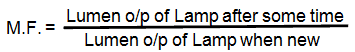
It is less than or equal to 1.
Typical values used for the lighting calculation are:
- 0.8 – For offices/classroom
- 0.7 – For clean Industry
- 0.6 – For dirty Industr
Read More: Light Emitting Elements And Their Types
Room Reflections
The room is considered to consist of three main surfaces:
- The ceiling
- The walls
- The floor
The effective reflectance’s of these 3 surfaces affect the quantity of reflected light received by the working plane. Light colors like white, yellow will have more reflectance compared to dark colors like blue, brown.
Utilization Factor
Utilization factor (UF) is the ratio of effective luminous flux to the total luminous flux of light sources. It is the measure of the effectiveness of the lighting scheme.
It depends upon
- The efficiency of luminaire
- The luminaire distribution
- The geometry of the space
- Room reflectance’s
- Polar curve
Read more: What is Energy Efficient Lighting and Techniques to Implement It
Space to Height ratio
It is the ratio of distance between adjacent luminaires (centre to centre) to their height above the working plane.
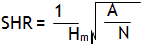
Where,
- Hm = Mounting height
- A = Total floor area
- N = No. of Luminaires
It should not exceed maximum SHR of the luminaire as provided by the manufacturer.
Note: A normal living room requires 20 lm/ft2 i.e. 215 lm/m2
For Studying room i.e. Classroom 300 lm/m2 is required.
(Note that for different environment and conditions there are different standards. For example companies like many MNC’s should maintain 600 lm/m2 in the Office’s for people working in night shifts)
Now let’s start with the steps. Consider the following layout of a particular floor of the School and analyse the lighting requirements of different sections of the floor.
For ease of the calculation all the light fittings and their ratings taken into account are of Phillips make. You can check the various fixtures and their specification here provided by Philips.
Click image to enlarge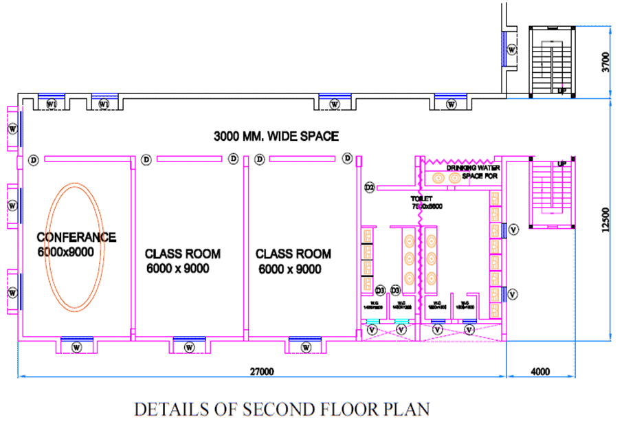
Lighting Design Calculation for Classroom
Cross section area of classroom = 6×9 = 54 m2, h = 3m
Lumens required = 54×300 = 16200 lm
The below table is a reference table for calculating Utilisation factor for light fittings. It differs from model to model and make to make. For just understanding the concept we are using a single reference table for all the light fittings. The actual table is provided by the manufacturer and can be little different from the one below.
| Room Reflectance |
Room Index |
| C |
W |
F |
0.75 |
1 |
1.25 |
1.50 |
2.00 |
2.50 |
3.00 |
4.00 |
5.00 |
| 0.70 |
0.50 |
0.20 |
0.43 |
0.49 |
0.55 |
0.60 |
0.66 |
0.71 |
0.75 |
0.80 |
0.83 |
|
0.30 |
|
0.35 |
0.41 |
0.47 |
0.52 |
0.59 |
0.65 |
0.69 |
0.75 |
0.78 |
|
0.10 |
|
0.29 |
0.35 |
0.41 |
0.46 |
0.53 |
0.59 |
0.63 |
0.70 |
0.74 |
| 0.50 |
0.50 |
0.20 |
0.38 |
0.44 |
0.49 |
0.53 |
0.59 |
0.63 |
0.66 |
0.70 |
0.73 |
|
0.30 |
|
0.31 |
0.37 |
0.42 |
0.46 |
0.53 |
0.58 |
0.61 |
0.66 |
0.70 |
|
0.10 |
|
0.27 |
0.32 |
0.37 |
0.41 |
0.48 |
0.53 |
0.57 |
0.62 |
0.66 |
| 0.30 |
0.50 |
0.20 |
0.30 |
0.37 |
0.41 |
0.45 |
0.52 |
0.57 |
0.60 |
0.65 |
0.69 |
|
0.30 |
|
0.28 |
0.33 |
0.38 |
0.41 |
0.47 |
0.51 |
0.54 |
0.59 |
0.62 |
|
0.10 |
|
0.24 |
0.29 |
0.34 |
0.37 |
0.43 |
0.48 |
0.51 |
0.56 |
0.59 |
| 0.00 |
0.00 |
0.00 |
0.19 |
0.23 |
0.27 |
0.30 |
0.35 |
0.39 |
0.42 |
0.46 |
0.48 |
UTILISATION FACTOR TABLE FOR SHRRoom = 1.5
Reflectance code for classroom = 752
i.e. 70% reflectance for ceiling, 50% for wall and 20% for floor (General standard for white/light coloured walls)
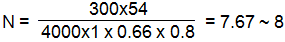
For R.I. = 1.8 and reflectance code = 752, Utilization Factor(U.F) = 0.66
For Classroom/Office Maintenance Factor = 0.8 (Standard)
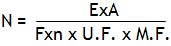
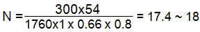
Where N = Number of luminaire required for given area
- E = Average luminance over the horizontal working plane
- A = Area of the horizontal working plane
- n = Number of lamps in each luminaire
- F = Lighting design lumens per lamp, i.e. initial bare lamp luminous flux
- UF = Utilisation factor for the horizontal working plane
- M.F. = Maintenance factor
You may also read: Star and Delta Connected Lighting Loads
If we use Philips Green Perform LED Batten Of 40W
Lumen/Watt: 4000lm/40w
Lamp Colour: Neutral White 4000K
Colour Rendering Index >80
Lifetime L70* : 50,000 hours
Lighting Design Calculation for Conference Room
Cross section area of Conference Room = 6×9 = 54 m2, h = 3m
Lumens required = 54×300 = 16200 lm
- For R.I. = 1.8 and reflectance code = 752, Utilization Factor (U.F) = 0.66
- M.F. = 0.8 (Standard)
If we use Philips Ultraslim Round LED Panel Light 22 W
Lumen/Watt: 1760 lm/22 W
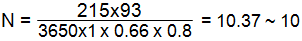
Lighting Design Calculation for Hall
Cross section area of hall = 31×3 = 93 m2, h = 3m
Lumens required = 93×215 = 19995 ~20000 lm

- For R.I. = 1.82 and reflectance code = 753, Utilization Factor (U.F) = 0.66
- M.F. = 0.8 (Standard)
If we use Philips MASTER TL5 High Efficiency ECO 35 W
Lumen/Watt: 3650 lm/35 W
Colour Rendering Index – 85
Average Lifetime: 25,000 hours
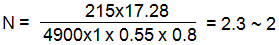
Lighting Design Calculation for Stair case Wiring
Note: read more about Stair Case wiring installation.
Cross section area of stair case = 6.4×2.7 = 17.28 m2, h = 3m
Lumens required = 17.28×215 = 3715 lm

For R.I. = 1.26 and reflectance code = 752, Utilization Factor (U.F) = 0.55
M.F. = 0.8 (Standard)
If we use Philips MASTER TL5 HIGH EFFICIENCY ECO 35 W
Lumen/Watt: 3650 lm/35 W
Colour Rendering Index – 85
Average Lifetime: 24,000 hours
Lighting Design Calculation for Toilet WC
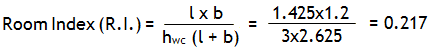
- Cross section area of WC Toilet 1&2 = 1.425×1.2 = 1.71 m2, h = 3m
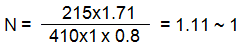
Lumens required = 1.71×215 = 367 lm
- For R.I. <0.75 Utilization Factor (U.F) table not applicable
- M.F. = 0.8 (Standard)
If we use Philips TL Miniature 8 W
Lumen/Watt: 410 lm/8 W
Colour Rendering Index – 60
Average Lifetime : 10,000 hours
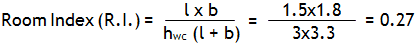
- Cross section area of WC Toilet 3&4 = 1.5×1.8 = 2.7 m2, h = 3m
Lumens required = 2.7×215 = 580 lm
 For R.I. <0.75 Utilization Factor (U.F) table not applicable
- M.F. = 0.8 (Standard)
If we use Philips MASTER TL5 HIGH EFFICIENCY ECO 14 W
Lumen/Watt: 1350 lm/14 W
Average Lifetime : 40,000 hours
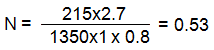
- So we can use single LED tube in sharing for both the bathrooms.
Lighting Design Calculation for Toilet Washroom Area
Cross section area of Washroom = 6×6.6 = 40 m2, h = 3m
Lumens required = 49.5×215 = 10642 lm

- For R.I. = 1.05 and reflectance code = 752, Utilization Factor (U.F) = 0.49
- M.F. = 0.8 (Standard)
If we use Philips Pacific LED Waterproof Batten 35 W
- Lumen/Watt: 4200 lm/35 W
- Colour Rendering Index – 85
- Average Lifetime: 50,000 hours

Note: The luminaires should be placed equidistance to each other for uniform distribution of light in the room. The actual number of luminaires used in the classroom will be less than what we have calculated since the utilization factor of LED lights is better than what we have taken in the calculation although steps will be the same.
You may Also Read:
The post Lighting Design Calculation in a Building – Step by Step appeared first on Electrical Technology.
March 07, 2017 at 01:56AM