All Day Efficiency of Transformer/ Distribution Transformer All Day Efficiency

All Day Efficiency of Transformer/ Distribution Transformer All Day Efficiency

In our previous articles we have discussed transformer working,construction etc.To day we discuss one of the important parameter of distribution transformer I.e, "all day efficiency of a distribution transformer".We know for a transformer, the efficiency is defined as the ratio of output power to input power.

Transformer Efficiency= Output Power /Input Power 

The above equation is efficiency of any transformer. But for some special types of transformers such as distribution transformers power efficiency is not the true measure of the performance.For that purpose distribution transformer we calculate all day efficiency.Distribution transformer serve residential and commercial loads.


The load on distribution transformers vary considerably during the period of the day. For most period of the day these transformers are working at 30 to 40 % of full load only or even less than that. But the primary of such transformers is energised at its rated voltage for 24 hours, to provide continuous supply to the consumer.

The core loss which depends on voltage, takes place continuously for all the loads. But copper loss depends on the load condition. For no load, copper loss is negligibly small while on full load it is at its rated value. Hence power efficiency can not give the measure of true efficiency of such transformers. in such transformers, the energy output is calculated in kilo watt hour (kWh). Then ratio of total energy output to total energy input (output + losses) is calculated. Such ratio is called energy efficiency or All Day Efficiency of a transformer.

Based on this efficiency, the performance of various distribution transformers is compared. All day efficiency is defined as,


While calculating energies, all energies can be expressed in watt hour (Wh) instead of kilo watt hour (kWh). Such distribution transformers are designed to have very low core losses. This is achieved by limiting the core flux density to lower value by using a relative higher core cross-section i.e. larger iron to copper weight ratio.

The maximum efficiency in such transformers occurs at about 60-70 % of the full load. So by proper designing, high energy efficiencies can be achieved for distribution transformers. The calculation of all day efficiency for a transformer will be posted soon.

Related:

maximum efficiency of distribution
transformer all day efficiency of transformer pdf 
efficiency of transformer formula
all day efficiency of transformer ppt
all day efficiency of transformer examples
distribution transformer efficiency in 24hrs


December 31, 2016 at 12:26AM by EEE, ADBU

Power SystemS Book by C L Wadhwa PDF Free Download

Power SystemS Book by CL Wadhwa PDF Free Download

As our part of free ebooks for electrical engineers today we are uploading  Power System book by C L Wadhwa it is a very important book of power systems . Power systems is a very important topic of electrical engineering to understand that well you need to read good book of that.So here we are sharing Electrical power systems by cl wadhwa.

Now you can download or read online Power SystemS Book by C L Wadhwa PDF to computer or mobile.
Image result for download electrical power systems 1 cl wadhwa ebook

Electrical Power System By CL Wadhwa Free Download


cl wadhwa power system google books
cl wadhwa power system objective questions pdf
power system pdf books
cl wadhwa power system solutions
c l wadhwa books
cl wadhwa basic electrical engineering pdf
power system by j b gupta pdf
power system book by vk mehta pdf free download


December 26, 2016 at 05:45PM by EEE, ADBU

http://ift.tt/2ijEyYu Current Components in a Transistor | Electrical4u www.electrical4u.com

http://ift.tt/2ijEyYu
safe_image.php?d=AQDxTA8OmCxhSc9K&w=130&


What is Energy Efficient Lighting and Techniques to Implement It

Energy Efficient Lighting & How to Implement It

It has been estimated that lighting accounts for about 20% of the total power generation of the world. The quality and quantity of light not only affects our health, comfort, safety and productivity but also affects the economy. Many nations have been spending a huge amount of their electricity budget on lighting.Energy Efficient Lighting & How to Implement It

For achieving efficient use of electricity, nations have been taking a sustained switch to the energy efficient lighting which is the most cost effective and reliable method of energy-saving. A well known technologies have been in use in the area of lighting to optimize the existing controls and lighting equipment for reducing the energy consumption with higher lighting quality. Let us discuss in detail about this concept.

What is Energy Efficient Lighting?

When the energy usage of a product is reduced without affecting its output or final response or user comfort levels is referred as energy efficiency. An energy efficient product consumes less energy to perform the same function when compared to the same product with more energy consumption.

The energy efficiency in the lighting sector gives the required illumination level of the lighting scheme for the application it has been designed for, while consuming the least amount of energy. Simply, energy efficient lighting can save the electricity while maintaining good quality and quantity of the light.What is Energy Efficient Lighting

Energy efficient lighting involves in replacement (or re-lamping) of traditional lamps (such as incandescent lamps) with that of energy efficient such as fluorescent lamps, CFL lamps and LED lamps. It also incorporates proper lighting controls such as timer controls, PIR and ultrasonic sensors based controls, etc.

It includes the turning off lights automatically when they are not in use, especially during daylight. It uses electronic chokes instead of ballasts in case of conventional lighting and also with the use of electronic circuitry; it can achieve dimming of lights when necessary.

These energy efficient schemes can be applied for external lighting, internal lighting for residential buildings and internal lighting for commercial buildings. These schemes not only reduce the energy consumption, but also enhance the lighting quality, increase the safety and staff well-being, and reduce the environmental impacts.

What is the Need for Energy Efficient Lighting?

Lighting is the basic requirement of any facility and it impacts the day-to-day activities of the people. This accounts a considerable amount of total energy consumption in domestic, commercial and industrial installations.

In industries, energy consumption for lighting constitutes only a small component of the total energy consumed, which is nearly 2-5 percent of total energy consumption. It accounts for 50 to 90 per cent in the domestic sector and it may go up to 20-40 percent in case of commercial /building sectors, information technology complexes, and hotels.

So it becomes an important area wherein energy to be conserved, especially in the domestic sector. Lighting efficiency solutions therefore play a key role in energy saving opportunities.

What is the Need for Energy Efficient Lighting?

Due to the high energy consumption, traditional incandescent lamps and high discharge lamps have to be substituted with energy efficient lamps. Traditional lamps not only consume large amounts of electric power, but they use much of its consumed energy to produce heat rather than light (for instance 90% of consuming energy in case of incandescent lamps).

With the installation of energy efficient lighting, the amount of energy consumption eventually will get reduced and it results in lower electricity bills.

Hence the energy efficient lighting is necessary

  • To reduce electricity consumption, thereby reduces the electricity bills
  • To save electricity rather than wasting in terms of losses
  • To lower greenhouse emissions because conventional lamps cause CO2 emissions
  • To achieve peak load reduction

You may also read: How much Watts Solar Panel We need for our Home Electrical appliances?

Tips, Tricks & Techniques to Implement Energy Efficient Lighting

The best and effective solution for energy conservation is the adoption of energy efficient lighting technologies in the lighting sector, which facilitates comprehensive redesigning of lighting and control systems.

There have been major improvements and innovations in lighting technologies which can offer a great potential for energy savings in many lighting applications such as household lighting, street lighting, hospitality and retail spotlights, office and industrial lighting, etc.

The following are the techniques or types of energy efficient lighting which are commonly practiced as energy-saving opportunities.

Techniques to Implement Energy Efficient Lighting

  1. Re-lamping with Energy-Efficient Lights

Energy efficient lamps can deliver the same amount of lighting with greater energy saving at low cost, when compared with conventional lamps. Traditional incandescent lamps consume a lot of energy to produce light in which 90 percent of consumed energy is given off as heat and also they consume more energy, typically 3-5 times more than the actual amount to produce light.

Energy efficient lamps overcome these problems by offering many more advantages than incandescent lamps. The two most popular choices of energy efficient light bulbs include CFLs (compact fluorescent lamp) and LED (light emitting diode) lamps.

Relamping with energy efficient lamps

Compact Fluorescent Lamps (CFLs)

CFL lamps are miniature or curly versions of long-sized fluorescent tubes. These lamps combine the efficiency of fluorescent lighting with the popularity and convenience of incandescent fixtures.

They screw in to the fixtures that allow all standard incandescent lamps, but not into standard fluorescent fixtures of long tubes. Depending on the brand and application use, they come in different range of styles, colors and sizes.

CFLs use 75 percent less energy and produce 75 percent less heat for producing the same amount of illumination as compared with incandescent lamps. They last 10 to 15 times longer and cost 10 to 20 more as compared to incandescent lamps.

CFL lamp working

These lamps are made with a phosphorous glass tube consisting of inert gas (argon) and mercury vapor. They use an electronic ballast to create high voltage during the starting and it can be a separate unit or permanently built in lamp. Some special and older models of CFLs come with separate ballast while some CFLs come with inbuilt ballast.

When an electric current is passed through the electrodes, the electrons that are bound to mercury atoms are excited which in turn emits ultraviolet light. As UV light strikes the fluorescent coating, it will be converted into visible light.

There are different types of CFL lamps available in today’s market. Some of these are spiral lamps, triple tube lamps, standard lamps, globe lamps, flood lamps and candelabra lamps. In case of replacing incandescent lamps, CFLs are chosen to match lumens that indicate the amount of light being generated as shown in figure below.Comparison of CFL with incandescent

These are available in a variety of light colors such as warm white and soft white, cool white and bright white, etc. depending on the type of application. The table below illustrates a range of light colors of CFLs for specific application.CFL types based on color

Light Emitting Diodes (LEDs)

LEDs are solid state semiconductor devices and are more energy efficient than even CFLs. They produce little heat and higher quality lighting than any other lamp. At the time of inception the usage of LEDs was limited as single bulb indicators in electronic circuits.

Later a number of LEDs are clustered to develop small lamps in battery powered devices such as charging lights, flashlights, etc. Today, LED lamps are available in many new bulb styles which are bright enough to replace traditional incandescent lamps.

Light Emitting Diodes (LEDs) LED lamps

LED lamps use 75 percent less energy than traditional incandescent and 50 percent less energy than that of a CFL. They can last 8-25 times longer compared to incandescent and up to four times longer than a CFL. Unlike incandescent and CFLs, LED lamps produce no heat and hence they are cool enough to touch. But, these are more expensive; however, they are affordable over the long run.

Energy efficient LED Lamps

LEDs are made up of semiconductor materials to form PN junctions. Whenever current flows across these junctions, it releases the energy in the form of a light. The wavelength and hence the color of the light depends on the composition of materials. LEDs can generate yellow, red, blue, green and white light. For lighting purpose several white color LEDs are stacked as clusters to produce required lighting for an application.

LED bulbs are available in different shapes, sizes and styles according to the type of application it is intended for. Some of these types include diffused bulbs, dimmable globe LED bulbs, track lighting pin-base type bulbs, flood reflector screw-in base bulbs, flame tip candelabra base LEDs and LED tube lights.

  1. Improving Lighting Controls

Lighting can be controlled with the use of various sensors to allow the operation of lamps whenever they are needed. These sensors detect the presence of humans, motion, timing or occupancy and based on the sensor output, it switches the lamps ON and OFF. Types of these controls include infrared sensors, automatic timers, motion sensors (PIR and ultrasonic sensors), and dimmers.

Photo sensors monitor the daylight conditions and accordingly send the signals to main controller to turn the lamps automatically off at dawn and on at dusk. This type of lighting control is commonly used with street lighting and outdoor lighting.

Motion Sensor Lights

Street lighting is another major area of energy conservation as it contributes considerable power consumption especially in the highways. Centralized control systems are most commonly used in street light control.

The popular centralized control is the SCADA (supervisory control and data acquisition) system which ensures remote control of operation of street lights from a central location. GSM/GPRS based systems also used to perform the remote control operation of street lights.

Street light control using GPRS GSM

  1. Replacing of Existing Fixtures and Ballasts

Replacing energy inefficient accessories with new energy efficient fixtures and ballast gives superior energy savings, longevity, and reliability. The main function of a luminaire or lighting fixture is to distribute, direct and diffuse light.

Some fixtures can absorb more than half of the illumination emitted the bulb that reduces the efficiency of the lighting. The higher efficiency fixtures can emit more light and hence one can save energy and money. Such fixtures consist of reflectors to direct the light in a desired direction.

energy efficient lighting fixtures

All discharge lamps require a ballast for achieving required operation. Conventional magnetic type ballasts cause power losses which is typically 15 percent of the lamp wattage. It also can raise fixture temperature during operation. So the proper ballast must be chosen to reduce ballast losses, fixture temperature and system wattage. In today’s market, many electronic or solid state types of ballast are available which can save 20 to 30 percent energy consumption over standard ballasts.

You may also read:

The post What is Energy Efficient Lighting and Techniques to Implement It appeared first on Electrical Technology.


December 23, 2016 at 05:18AM

Synchronization of three Phase Alternators and Synchronization by Synchroscope


Synchronization of Three-Phase Alternators:

The conditions to be satisfied for synchronization of three phase alternators are same as that for single phase alternators.As discussed earlier the following are conditions for synchronization of alternators:

i) The terminal voltage of the incoming machine must be same as that of bus bar voltage. 

ii) The frequency must be same as that of the incoming machine as well as that of the bus bar. This necessitates that speed must be properly adjusted  (f = PN/120).

iii) Phase sequence for the two voltages must be same with respect to the external load.

But instead of saying that voltages must act in phase opposition, the phase sequence must be same i.e. phases must be connected in proper order of R, N, B. Typical setup for synchronization of three Phase alternators is shown in the below figure. 

synchronization-of-three-phase-alternators-and-by-synchroscope


In synchronizing three phase alternators, three lamps are connected as shown in the below figure, so that it can be used to indicate whether the incoming machine is running slow or fast. With the symmetrical connection of lamps, they would dark out or glow up simultaneously provided that phase sequence is same for incoming machine and bus bar.

            Consider the two alternators A and B to be synchronized. The alternator A is already running at synchronous speed and its excitation is so adjusted that it builds up the rated voltage. The alternator A is connected to the bus bars of constant voltage and frequency.The alternator B is to be connected to bus bar i.e. it is to be synchronized with alternator A. The process of synchronization of three Phase Alternators can be explained as below:

Step 1: Start the prime mover of the machine.Adjust its speed to a synchronous speed of machine B. This will rotate the rotor of alternator B at synchronous speed. 

Step 2: The switch S4 is then closed. By adjusting the rheostat Rx the excitation to the field is adjusted so that induced e.m.f. of B is equal to the induced e.m.f. of A. This can be verified by a voltmeter. 

Step 3. To satisfy remaining conditions, the three lamp pairs are used which are L1, L2, and L3 as shown in the above figure.These are connected in such a way that pair L1 is straight connected while the pairs L2 and L3 are cross connected. 


synchronization-of-three-phase-alternators-and-by-synchroscope

To understand the connection, the pairs are again shown in the above figure.Now two supplies are supplying lamp pairs, ERYB i.e. voltage supply of bus bar while ER'Y'B'. i.e. supply generated by alternator B. The switch S3 is still open.
synchronization-of-three-phase-alternators-and-by-synchroscope
 Let the three bus bar voltages be represented by phasors OR, OY, OB rotating at angular of ω1 rad/s. The incoming alternator voltages are represented by phasors OR', OY', OB' rotate angular speed of ω2 rad/s.The phasor ERR', joining the tips R and R' is the voltage across lamp pair L1. Similarly, EYB' and EBY' are voltages across lamps L2 and L3 respectively. 
          If there is a difference between the two frequencies due to the difference in speeds of the two alternators, the lamps will become dark and bright in a sequence. This sequence tells whether incoming alternator frequency is less or greater than machine A. 
           The sequence L1, L2, L3 tells that machine B is faster as the voltage star R'Y'B'  will appear to rotate anticlockwise with respect to bus bar voltage RYB at a speed corresponding to the difference between their frequencies shown in the below figure.The sequence L3, L2, L1 tells that the machine B is slower because voltage star R' Y' B' will appear to rotate clockwise with respect to bus bar voltage RYB.The prime mover speed can be adjusted accordingly to match the frequencies. 
        The synchronization of three Phase alternators is done at the moment when Lamp L1 is in the middle of the dark period. If the lamps pair becoming dark and bright simultaneously, it indicates incorrect phase sequence which can be corrected by interchanging any two leads either of the incoming machine or of bus bars.

synchronization-of-three-phase-alternators-and-by-synchroscope

Key Point: For high voltage alternators, it is not possible to use the lamps directly.In such cases, lamps are through potential transformers.

              In this method of synchronization of three phase alternators when lamp L1 is dark the other two lamp pairs L2 and L3 and equally bright.So this method of synchronization is called "Lamps bright and dark" method.
Synchronization by Synchroscope:

          It can be seen that the method described in earlier section i.e. Lamp method is not accurate since it requires a correct sense of judgement of the operator.Hence to avoid the personal judgement, the machines are synchronized by an accurate device known as synchroscope. 
       It consists of a rotating pointer which indicates the exact moment of closing the synchronizing switch.If the pointer rotates in an anticlockwise direction, it indicates that incoming machine is running slow whereas clockwise rotation of pointer indicates that incoming machine is running faster.The rotation of pointer is proportional to the difference in the two frequencies.The pointer should rotate at a very low speed in the direction of the arrow marked fast as shown in the below figure. 
synchronization-of-three-phase-alternators-and-by-synchroscope
Synchronization by Synchroscope
synchronization-of-three-phase-alternators-and-by-synchroscope

           When the rotating pointer reaches the vertical position at slow speed the switch must be closed. The pointer will oscillate about some mean position instead of rotating if the difference in frequencies is large. In such cases, the speed of the incoming machine is adjusted properly.
        The connections for Synchronization by Synchroscope are shown in the above figure.Any two bus bar connected to its terminals while its other terminals are connected to corresponding lines of the incoming machine. The phase sequence form bus bar and from the machine must be same.It can be checked with the help of phase sequence indicator. The voltmeter is used to check the equality of voltages of the bus bar and incoming machine. The Synchronization by Synchroscope procedure is already explained before. 


December 22, 2016 at 06:48PM by EEE, ADBU

http://ift.tt/2hK0ryO Voltage Multiplier | Electrical4u www.electrical4u.com

http://ift.tt/2hK0ryO
483710_305689999558322_769456670_n.png?o


What are Industrial Communication Networks? An Overview

An Overview of Industrial Communication Systems & Networks

An industrial communication network is a backbone for any automation system architecture as it has been providing a powerful means of data exchange, data controllability, and flexibility to connect various devices. With the use of proprietary digital communication networks in industries over the past decade led to improve end-to-end digital signal accuracy and integrity.

These networks, which can be either LAN (Local Area Network, which is used in a limited area) or WAN (Wide Area Network which is used as global system) enabled to communicate vast amounts of data using a limited number of channels. Industrial networking also led to the implementation of various communication protocols between digital controllers, field devices, various automation related software tools and also to external systems.

What are Industrial Communication Networks

As the industrial automation systems become complex and large with more number of automation devices on control floor, today, the trend is toward Open Systems Interconnection (OSI) standards that permits to interconnect and communicate any pair of automation devices reliably irrespective of the manufacturer.

With the advancements in digital technology, fieldbus technology is now ruling the automation field as it provides multidrop communication facility that results cost effective and cable saving communication. The following is an overview of some industrial communication networks that play a significant role in today’s industrial control systems.

What is an Industrial Communication Network?

Data communication refers to the transformation of information or data, mostly in digital format from a transmitter to a receiver through a link (which can be copper wire, coaxial cable, optical fiber, or any other medium) connecting these two.

Traditional communication networks are used to enable data communication between computers, computers and its peripherals and other devices. On the other hand, industrial communication network is a special type of network made to handle real-time control and data integrity in harsh environments over large installations.

The examples of industrial communication networks include Ethernet, DeviceNet, Modbus, ControlNet, and so on.

What is industrial network

The three significant control mechanisms used in industrial automation field include Programmable Logic Controllers (PLCs), Supervisory Control and Data Acquisition (SCADA) and Distributed Control System (DCS). All these elements deals with field instruments, smart field devices, supervisory control PCs, distributed I/O controllers and HMI suits.

In order to provide an interconnection between these devices and also to enable communication in between them, a powerful and more effective communication network or scheme is needed. They differ quite significantly from traditional enterprise networks. These industrial networks form a communication path among field devices, controllers and PCs.

The transmission media for passing the data and control signals can be either wired or wireless. In case of wired transmission, a cable is used that can be a twisted pair, coaxial cable or fiber optics. Each network cable has its own electrical characteristics that may be less or more suitable to a type of network or specific environment. In case of wireless transmission, communication is performed through radio waves.What is an Industrial Communication Network?

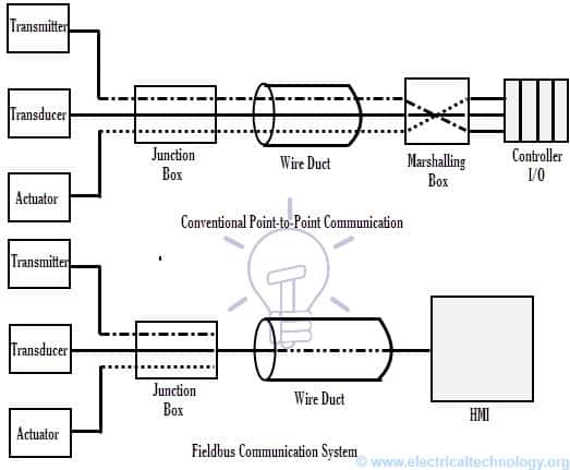
A fieldbus is another local control area network used for real-time distributed control systems in complex automated industrial systems. It is a digital two-way multidrop communication link between controllers and intelligent field devices such as smart sensors/actuators/transducers. It replaces the conventional point-to-point communication system that consists of as many wire pairs as the number of field devices.

In case of fieldbus system two wires are enough for many devices that belong to the same segment. This result, enormous cable saving thereby, cost effective. Profibus and Foundation Field Bus are the two most dominant fieldbus technologies used in process automation field.

Hierarchical Levels in Industrial Communication Networks

Earlier we have discussed the hierarchical arrangement of the automation system depending on their functionality and information flow in Industrial Automation article. In a manufacturing or process industry, the information or data flows from field level to enterprise level (bottom-to-top) and vice-versa.

Different levels have to handle different requirements of a particular level. So it is obvious that no single communication network address requirements needed by each level. Hence different levels may use different network based on the requirements such as data volume, data transmission, data security, etc. Based on the functionality, industrial communication networks are classified into three general levels which are discussed below.
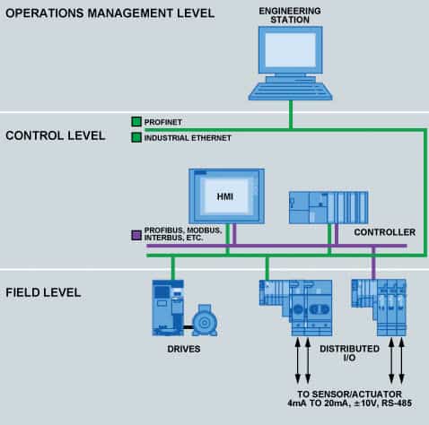
Hierarchical Levels in Industrial Communication Networks

Device Level:

This lowest level consists of field devices such as sensors and actuators of processes and machines. The task of this level is to transfer the information between these devices and technical process elements such as PLCs. The information transfer can be digital, analog or hybrid. The measured values may stay for longer periods or over a short period.

In order to provide field level communication, 4-20 mA current loop, serial point-to-point communication methods are widely used. These networks consist of parallel, multiwire cables as transmission medium. The common serial communication protocol standards used in this level include RS232, RS422 and RS485. There are many other field level communication networks available which are characterized different factors such as response time, message size, etc.

Nowadays, fieldbus technology is the most sophisticated communication network used in field level as it facilitates distributed control among various smart field devices and controller. This is a bidirectional communication system in which many variables are taken care by single transmission. Different types of fieldbuses include HART, ControlNet, DeviceNet, CAN Bus, Profibus, and Foundation Field Bus.

Control Level:

This level consists of industrial controllers such as PLCs, distributed control units, and computer systems. The tasks of this level include configuring automation devices, loading of program data and process variables data, adjusting set variables, supervising control, displaying variables data on HMIs, historical archiving, etc. So this level requires characteristics like short response time, high speed transmission, short data lengths, machine synchronization, constant use of critical data, etc.

Local Area Networks (LANs) are widely used as communication networks in this level to achieve desired characteristics. The Ethernet with TCP/IP protocol is mostly used as control level network to connect control units with computers. In addition, this network acts as a control bus to coordinate and synchronize between various controller units. Some fieldbuses are also used in this level as control buses such as Profibus and ControlNet.

Information Level:

This is the top level of the industrial automation system which gathers the information from its lower level i.e., control level. It deals with large volumes of data that are neither in constant use or time critical. Large scale networks are exists in this level. So Ethernet WANs are commonly used as information level networks for factory planning and management information exchange.  Sometimes these networks may connect to other industrial networks via gateways.

Commonly used Industrial Networks

There exist many different communication networks designed to interconnect industrial field devices and various I/O modules. These are described based on certain protocols. A protocol is a set of rules that are used in communication between two or more devices. Based on these protocols, communication networks are classified into many types. Some common and popular industrial communication standards are described below.

Serial Communication

Serial communication is the basic communication system provided for every controller such as a PLC. This communication is implemented by using protocol standards such as RS232, RS422 and RS485. The acronym RS stands for Recommended Standard which specifies serial communication characteristics in terms of electrical, mechanical and functional features.

Serial communication interfaces are either built into the CPU or process module (consider, for a Programmable Logic Controller) or it can be a separate communication module. These RS interfaces are mainly used to transfer the data reasonably at high data rate between a PLC and the remote device. Barcode readers, operator terminals and vision systems are the examples of these interfaces.Serial Communication in PLC

RS-232 serial communication is designed to support one transmitter and one receiver and hence it offers communication between one controller and one computer. The maximum cable length should be up to 50 feet. RS 422 (1Tx, 10 Rx) and RS485 (32Tx, 32 Rx) serial communication standards are designed to communicate between one computer and many controllers. These standards are limited to lengths of 1650 feet (in case of RS422) and 650 feet (in case of RS485).

HART:

It is an acronym for Highway Addressable Remote Transducer. It is an open process control network protocol that superimposes digital communication signal on the top of 4-20mA signals using the Bell 202 Frequency Shift Keying (FSK) technique.

It is the only communication network that facilitates both analog and bidirectional digital communication at the same time by the same wiring, and hence these networks are also called as hybrid networks. This digital signal is called as HART signal which carries diagnostic information, device configuration, calibration and other additional process measurements.

HART Communication Network

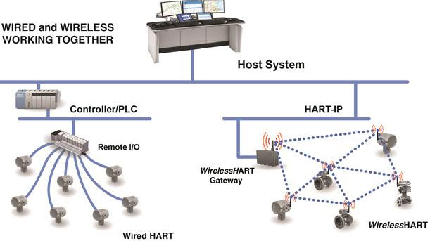
HART networks operate in either point-to-point or multidrop mode. In point-to-point mode, 4-20 mA current signal is used to control the process while HART signal remains unaffected. Multidrop HART networks are used when devices are widely spaced. HART-compatible multivariable smart field devices are widely used in many industries. HART communication network is mainly used in SCADA applications.

DeviceNet

It is an open-device level network based on CAN technology. It is designed to interface field level devices (such as sensors, switches, barcode readers, panel displays, etc.) with higher level controller (such as a PLC) with a unique adoption of basic CAN protocol. It can support up to 64 nodes and supporting up to 2048 total devices.

It reduces the network cost by integrating all devices on a four-wire cable that carries both data and power conductors. The power on the network allows the devices to be powered up directly from the network and hence it reduces the physical connection points. This network is popularly used in automotive and semiconductor industries.

ControlNet

It is an open control network, which uses Common Industrial Protocol (CIP) in order to combine the functionality of peer-to-peer network and an I/O network by providing high speed performance. This network is the combination of Data Highway Plus (DH+) and remote I/O. It is used for real-time data transfer of time-critical as well as non time-critical data between I/Os or processors on the same network.

It can communicate up to a maximum of 99 nodes with a data transfer rate of five million bits per second.  It was designed to be used on both device and field level of industrial automation system. It provides media and communication redundancy at all the nodes of the network.

ControlNet Communication Network

Modbus

It is an open system protocol that can run on a variety of physical layers. It is the most widely used protocol in industrial control applications. It is a serial communication technique which provides master/slave relationship to communicate between devices connected on network. It can be implemented on any transmission medium, but most commonly used with RS232 and RS485.

Modbus Comunication Network

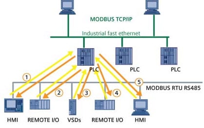
Serial Modbus with RS232 or RS485 (as physical layers) facilitates the connection of Modbus devices to the controller (such as a PLC) in a bus structure. It can communicate between one master and a number of slaves up to 247 with a data transmission rate of 19.2 kbits/s.

A newer version of Modbus TCP/IP uses Ethernet as physical layer that facilitates the data exchange between PLCs in different networks. Irrespective of the type of physical network, it facilitates a method of access and control of one device by another.

Profibus

It is one of the well known and widely implemented open-field networks. These networks are mainly used in process automation and factory automation fields. It is most suitable for complex communication tasks and time-critical applications. There are three different versions of Profibus namely, Profibus-DP (Decentralized Periphery), Profibus-PA (Process Automation) and Profibus-FMS (Fieldbus Message Specification).

Profibus Comunication Network

Profibus-DP is an open fieldbus communication standard that utilizes master/slave communication between network devices. It uses RS485 or fiber optic transmission technologies as physical layer media. It is mainly used to provide communication between controllers and distributed I/Os at device level.

Profibus-PA is specially designed for process automation. Profibus-PA networks are recommended to use in intrinsically safe areas. These networks permit sensors, actuators and controllers to connect to a single common bus, which provides data communication and power over bus. These networks use the Manchester Bus Powered (MBP) physical layer based on international standard IEC 61158-2.

Profibus DP, PA and FMS

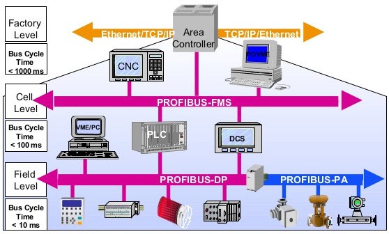
Profibus-FMS is a multimaster or peer-to-peer messaging format which allows master units to communicate with one another. It is a general purpose solution that performs communication tasks in control level, especially in cell sublevel to facilitate communication between Master PCs.

Most commonly FMS and DP are used simultaneously in COMBI mode in situations where a PLC is being used in conjunction with a PC. In such case primary master communicates with secondary master via FMS while DP transfers control data on same network to I/O devices.

Foundation Field Bus

It is an open fieldbus standard designed specially to meet the mission-critical demands in intrinsically safe environments. It is a type of LAN for foundation fieldbus compatible instruments and controllers used in manufacturing and process industries. It is a two-way, digital protocol standard defined by intrinsically safe IEC 61158-2 physical layer (for FF H1) and compatible with Ethernet equipment (in case of FF HSE). The three kinds of FF networks include low speed H1, high speed H2 and High Speed Ethernet HSE.

Foundation Field Bus

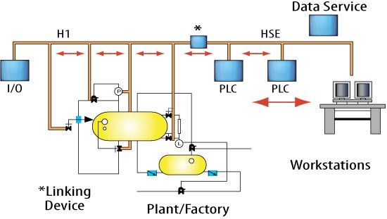
H1 network supports a speed of 31.25 kbps. There are two speeds supported by H2 network, which are 1.0 Mbps and 2.5 Mbps. HSE network supports 10 or 100 Mbps speed as it uses Ethernet protocol.

You may also read:

The post What are Industrial Communication Networks? An Overview appeared first on Electrical Technology.


December 19, 2016 at 08:29PM