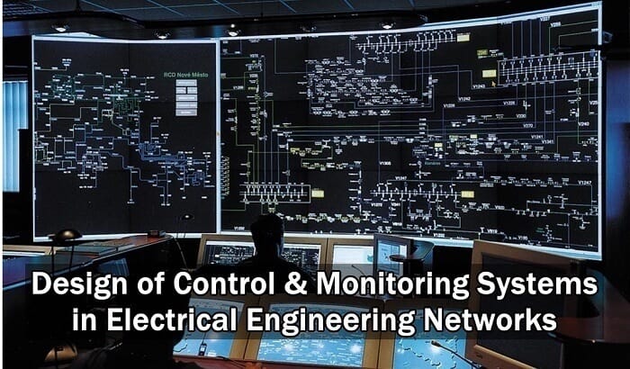
Design of Control & Monitoring Systems in Electrical Engineering

Design of Control & Monitoring Systems in Electrical Networks

Design Implementation

The preparation of the design of control and monitoring systems requires the definition of a set of actions:

  • Definition of equipments and systems to be controlled and monitored (all equipments – circuit breakers, instrument transformers, isolators, switches, etc. – must be identified by a code, defined by the Construction Owner or by the designer, if no instructions exist.
  • Definition of the type of control and monitoring to implement, according to the complexity of the installation.
  • Definition of protections units to use, establishing the tripping matrix.
  • Definition of the “set-points” of the protection units.
  • Definition of interlocking matrix.
  • Definition of operation sequences and sequential automatisms, if any.
  • Synchronization of MV, HV and EHV (MV: Medium Voltage; 1 kV < V < 60 kV. HV: High Voltage; 60 kV ≤ V < 150 kV. EHV: Extra High Voltage; V ≥ 150 kV) circuit breakers (closing in the condition “live bar – live line”).
  • Reclosing programme.
  • Definition of digital and analogue input and output signals .
  • Definition of general alarms and respective data treatment.
  • Definition of electric parameters to be monitored and measured.
  • Definition of time delays to be established.
  • Definition of disturbances to be recorded.
  • Establishment of switching programmes, under normal and emergency situations.
  • Definition of operation sequences and sequential automatisms, if any.
  • Load shedding, if required.
  • Interactions between equipments and/or systems (local and remote).
  • Events and respective data to be remotely transmitted.
  • Control and monitoring input signal from the remote control center(s).
  • General communication networks.

Design of Control & Monitoring Systems in Electrical Engineering Installations & networks

Documents to be Produced

Apart from single line diagrams of the global installation, showing all equipments and their codes and the protection units, it must be produced for each part of the installation and for each equipment to be controlled and monitored, the control and monitoring schematic diagrams, which are important pieces for maintenance and failures detection.

In these diagrams it must be represented all equipments to be controlled and monitored and control equipments, either manual or automatic (auxiliary relays, control switches, etc.), dully codified, interlocking (if any), as well as auxiliary contacts of protection units, pilot lights and metering equipment.

The above referred diagrams must be complemented by wiring diagrams of power and/or control switchgears, panels and cabinets, showing the respective terminal blocks, dully identified, with the connection of conductors of internal wiring and control cables. Each conductor must be identified with a label, defining the connection in accordance with was defined in the design documents.

A cable list must also be produced, showing:

  • Type of cable, number of conductors and cross section.
  • Cable origin and destination.
  • Cable identification, according to was defined in the design documents.
  • Cable routing.

Logic Diagrams & Operation Equations

Within the design of control and monitoring systems it must also be considered the programming instructions for microprocessed units of the system, which must include interlocking, tripping orders, equipment blocking situations and eventual sequential automatisms.

These instructions may be produced under as logic diagrams or operation equations.

a) Logic diagrams

Logic diagrams associated events (represented by capital letters) that traduce the conditions to be fulfilled to logic bloks of mathematic logical operations – logical conjunction (˄) and logical disjunction (˅).

It is assumed that an event A can have the following values:

  • A = 1 – event verified.
  • A = 0 – event not verified.

b) Operation equations

Operation equations use Boolean Algebra, establishing equations between the events (represented by capital letters), mathematic logical operations – logical conjunction (˄) and logical disjunction (˅) – to algebraic operations ( x ; + ).

For an event X it is assumed the following convention:

  • X – event verified.
  • – event not verified

Interlocking & Local Manual Control

In order to avoid wrong maneuvers that can damage the equipment and cause hazards to the employees an interlocking program must be implemented.

The most common wrong maneuvers in electrical installations are:

  • Open or close isolators with the circuit breakers closed (on load manoeuvre).
  • Close earthing switches with circuit breakers and/or isolators closed and with voltage present.
  • Close circuit breakers and/or isolators with earthing switches closed.
  • Close other circuit breakers when the protection relay 50BF is activated.

There are two types of interlocking: electrical and mechanical.

Electrical interlocking is intended to prevent non authorized electrical control and is performed through “hardware” (relays and cabling), through “software”, or a combination of both.

Mechanical interlocking is intended to prevent local manual control and can be achieved by padlocks and locks, or can be built-on, which is the case of isolators with earthing switches in substations.

Equipments can be provided with both electrical and mechanical interlocking.

Local manual control is performed close to the equipments. By safety reasons, this type of control, with the exception of emergency situations, is only possible to do when it is authorized by the person in charge of the operation of the electrical installation, which will get it “free” to be performed by a designated operator.

For manual control interlocking can only be superseded by personnel dully authorized:

Hardware” interlocking: using control switches with key, which is only accessible to authorized personnel.

Software” interlocking: using a “key word” that allows to supersede interlocking only to authorized personnel.

About the Author: Manuel Bolotinha

-Licentiate Degree in Electrical Engineering – Energy and Power Systems (1974 – Instituto Superior Técnico/University of Lisbon)
– Master Degree in Electrical and Computers Engineering (2017 – Faculdade de Ciências e Tecnologia/Nova University of Lisbon)
– Senior Consultant in Substations and Power Systems; Professional Instructor

The post Design of Control & Monitoring Systems in Electrical Engineering appeared first on Electrical Technology.


July 30, 2018 at 05:50PM by Department of EEE, ADBU: https://ift.tt/2AyIRVT
The network of data acquisition in a digital substation

The data acquisition in electric power system is very important and includes a lot of areas such as substation. Digital substation is one of the key parts of smart grid... Read more

The post The network of data acquisition in a digital substation appeared first on EEP - Electrical Engineering Portal.


View more at https://electrical-engineering-portal.com/network-data-acquisition-digital-substation
Credit- Electrical Engineering Portal. Published by Department of EEE, ADBU: tinyurl.com/eee-adbu

Protective Actions to Avoid & to Reduce Electric Hazardous

Protective Actions to Reduce & Avoid Electric Hazardous

General Rules

As general safety rules for EHV, HV and MV installations (EHV: Extra High Voltage – V ≥ 150 kV. HV: High Voltage – 60 kV ≤  V < 150 kV. MV: Medium Voltage – 1 kV < V < 60 kV), those related physical with the protection of the site, taking into account the access to the equipments and the basic principles of operation and maintenance of the equipments, are fundamental.

All applicable laws, internal and official regulations and national and/or international standards must be accomplished, in what concerns equipments and health and safety.

Protective Actions to Avoid & to Reduce Electric Hazardous

Indoors equipments must be installed in rooms with doors and lock, in order that only authorized people can reach them.

There are some actions that must be carried out in order to avoid the hazardous of electricity.

As general rules it must be considered:

  • Electrical installations must be easy to understand and properly maintained
  • Use of equipments with reduce voltage (≤ 25 V – humid or wet places – or ≤ 50V), whenever possible
  • Use of equipments with reinforced insulation
  • Adequate degrees of protection provided by enclosures (IP and IK codes)
  • Earthing of all metallic structures
  • All live metallic parts not enclosed must be segregated by means of fences or similar
  • Around switchboards it must exists enough space available for the circulation of personnel
  • Only specialized personnel, using appropriated tools must perform any work on electrical installations
  • In case of fire power supply must be immediately interrupted and the personnel must:
  • Give the alarm immediately
  • Use appropriated protection masks against toxic gases
  • Proceed to smoke exhaustion
  • Close all doors, windows and other openings, to avoid the spread of fire
  • Fight the fire using extinguishing portable equipment (ABC powder or CO2)

Related Article: All About Electrical Protection Systems, Devices And Units

To perform work on electrical installations the employees must follow very severe rules that must be in accordance with the laws and the regulations, and also with the internal procedures produced by the company.

The part of the installation subject of intervention must be de-energized and connected to the earth.

Employees must be equipped with protective clothing, helmet, glasses dielectric footwear and insulation gloves. An insulation mat shall be placed at the local of the intervention.

The working area must be delimited using barriers, tapes, fences or other similar equipments, in order to avoid the entrance of non authorized people.

After the conclusion of work, and before energizing, it must be assured that the work was done properly and that all personnel is aware that power is going to be connected.

Only the responsible of the employees in charge of work is allowed to reconnect power.

Safety Interlocks

In order to avoid wrong manoeuvers that can damage the equipment and cause hazards to the employees an interlocking programme must be implemented.

Most common wrong manoeuvers are:

  • Open or close isolators with the circuit breakers closed (on load manoeuvre).
  • Close earthing switches with circuit breakers and/or isolators closed and with voltage present.
  • Close circuit breakers and/or isolators with earthing switches closed.
  • Close other circuit breakers when the protection relay 50BF, “circuit breaker failure”, is activated.

Also Read: Transformers Fire Protection System – Causes, Types & Requirements

There are two types of interlocking: electrical and mechanical.

Electrical interlocking is intended to prevent non authorized electrical control and is performed through “hardware” (relays and cabling) and/or through “software”.

Mechanical interlocking is intended to prevent local manual control and can be achieved by padlocks and locks, or can be built-on, which is the case of isolators with earthing switches.

Equipments can be provided with both electrical and mechanical interlocking.

Equipments with Accessible Live Parts

All electrical equipments with accessible live parts, such as auxiliary transformers and capacitor banks, must be protected by a fence with a door locked with a padlock as shown on the figure below, in order to avoid the entrance of personnel with the equipment energized.

The fence must be connected to the earth grid and the door must be provided with a micro-switch to trip the protective device if by any chance any person tries to enter the area.

In case of capacitor banks the opening of the door must have a time delay interlocking to assure that the capacitor bank is completely discharged.

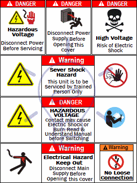
Electrical Safety Signs

At EHV, HV and MV installations electrical safety signs must be placed, stating the existence of electrical installations and that there is danger of electrocution.

These signs must be written in the language of the country where they are installed and they must comply with the applicable technical standards.

Electrical safety signs must be placed, at least, at all fences, doors of compartments with electrical equipment, metallic towers and structures, switchboards and batteries.

Electrical Safety Signs

About the Author: Manuel Bolotinha

-Licentiate Degree in Electrical Engineering – Energy and Power Systems (1974 – Instituto Superior Técnico/University of Lisbon)
– Master Degree in Electrical and Computers Engineering (2017 – Faculdade de Ciências e Tecnologia/Nova University of Lisbon)
– Senior Consultant in Substations and Power Systems; Professional Instructor

The post Protective Actions to Avoid & to Reduce Electric Hazardous appeared first on Electrical Technology.


July 29, 2018 at 09:57PM by Department of EEE, ADBU: https://ift.tt/2AyIRVT

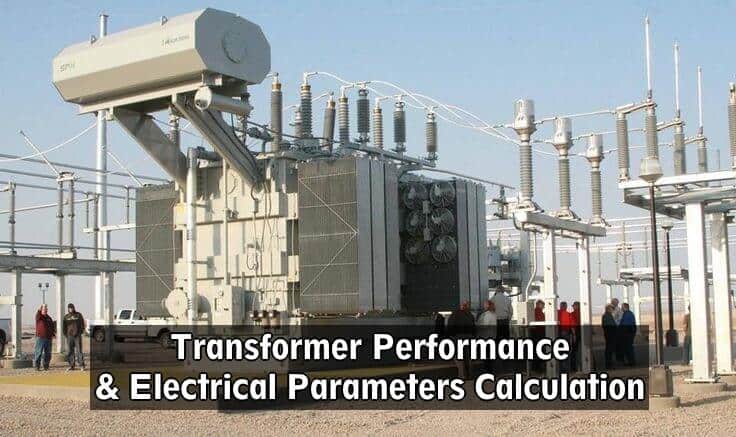
Transformer Performance & Electrical Parameters

Transformer Performance & Electrical Parameters Calculation

Rated Power of Transformer

Rated Power is the amount of power that a transformer can handle and it is limited by the size of the winding conductors, and by the corresponding amount of heat they will product when current is applied.

This heat is caused by losses, which results in a difference between the input and output power. Because of these losses, transformers are rated not in terms of kW or MW (active power), but in terms of kVA or MVA (apparent power).

Transformer Performance & Electrical Parameters Calculation

Rated Power is noted as “S”.

If a transformer as two cooling systems Rated Power of the transformer depends of the cooling method that is in use in a certain moment, and so at the name plate of the transformer two Rated Powers are indicated.

Considering a transformer with an ONAN / ONAF (Oil Natural Air Natural/Oil Natural Air Forced) cooling system, Rated Power of this transformer is, for example 30/40 MVA, 30 MVA corresponding to ONAN and 40 MVA corresponding to ONAF.

Rated Voltages, Ratio & Rated Frequency of Transformer

Rated Voltages of a transformer are the service voltage of the primary and of the secondary, V1 and V2, respectively.

The ratio of a transformer is the relation between the number of turns of primary winding and the number of turns of the secondary windings, and is noted as “a”.

Considering a transformer with N1 turns in the primary winding, N2 turns in the secondary winding, V1 and V2 the primary and the secondary voltages, and I1 and I2 the primary and the secondary currents, the ratio can expressed by the following equation:

a = N1 / N2 = V1 / V2 = I2 / I1

The rated frequencies are usually 50 Hz and 60 Hz.

Losses & Efficiency in Transformer

Transformers are subject to two types of losses:

  • PCu  : resistive losses (W)
  • P0    : iron losses or core losses (W)

The resistive losses, due to Joule effect on the windings, depends on the current that goes through the turns of the windings, which results from the loads connected to the transformer.

The iron losses, are the sum of hysteresis losses and eddy current losses, which happens even when the transformer has no load (due to this fact iron losses are also known as no-load losses).

Both resistive losses and iron losses are indicated by the transformer’s manufacturer.

It is common that transformers that are not in service permanently (example: public lighting transformers) are required to have reduced iron losses.

Also Read: Maintenance of Transformer – Power Transformers Maintenance, Diagnostic & Monitoring

Total losses (Pt) are given by the equation:

Pt = P0 + PCu (W)

Iron losses are determined from open circuit test and resistive losses from short circuit test.

Efficiency of a transformer (noted “η” and expressed in “%”) is defined as the ratio between the input and the output active power.

Considering a transformer with the following parameters:

  • Input   : P1 ; V1, I1
  • Output: P2 ; V2, I2
  • Load power factor : Cos Φ

Efficiency is then calculated according to the following equation:

Efficiency equation

Hence at any volt-ampere load, the efficiency depends on power factor; at unity power factor efficiency has its maximum value.

Impedance Voltage Drop in T/F

Impedance voltage drop of a transformer represents the internal resistance of the transformer, and is usually noted as “uk” and indicated in “%”.

The equivalent impedances of the transformer are calculated by the equations:

Primary side

Z =  uk(%)  x  U12 / 100 x Sn

Secondary side

ZT  =  uk(%)  x  U22 / 100  x  Sn

The values of the equivalent resistance and reactance of the transformer are given by the following equations:

R =  PCu  /  3xIn2

equivalent resistance and reactance of the transformerRelated Post: What is the normal or average life expectancy of a Transformer ?

Vector Group of Transformers

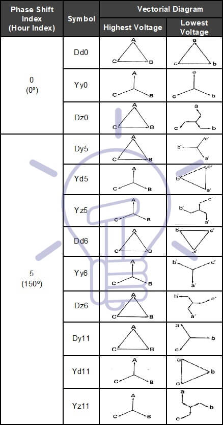
Vector group of three-phase transformers indicate the phase shift between primary and secondary voltages and the way the windings are connected.

Three-phase windings transformers can have “star” (Y/y), “delta” (D/d) [ In delta connection, windings are connected in triangle, so it is usual to represent this connections by Δ] and “interconnected star” / “zigzag” (Z/z) connections, being the most common star and delta.

If the transformer has tertiary windings, usually for harmonic compensations, (mainly 3rd harmonic) these windings have a “delta” connection.

Capital letters refer always to highest voltage and lower-case letters to lowest voltage.

When neutral point is accessible letter “N” or “n” is added to the symbol.

Table 1 shows the most common vector groups.

Table 1 – Common vector groups

Common vector groups of Transformer Common vector groups of Transformer

Most common connections are Y-Δ,  Δ-Y,  Δ-Δ and Y-Y; star-star is common in EHV and HV, although it presents imbalance and 3rd harmonic problems, being necessary the third winding above referred.

Star-Delta (Y-Δ) is frequently used as step down (EHV/HV); delta-delta (Δ-Δ) is commonly used for medium voltage (MV/MV transformers); delta-star (Δ-Y) is used in step-up transformer in a generation station and in MV/LV transformers.[EHV: Extra High Voltage (V ≥ 150 kV). HV: High Voltage (60 kV ≤ V < 150 kV). MV: Medium Voltage (1 kV < V < 60 kV). LV: Low Voltage (V ≤ 1 kV)]

Common groups in MV/LV power transformers are Dyn5 and Dyn11; for HV/MV power transformers is usual to have a vector group YNd11, and for HV/HV transformers is common to have YNyn0 and Ynyn1.

Voltage Regulation of Transformer

Electrical networks may have voltage fluctuations, due to load changing, network configuration and level of energy production.

For that reason is necessary to proceed to voltage regulation; Transformer regulation is done usually at the highest voltage windings of power transformers (because the current is lower).

Those windings must be provided with taps, voltage regulators and tap-changers.

At MV installations transformers have usually 5 taps (central point that corresponds to rated voltage and± 2×2.5 %taps) and off-load tap changer. The ratio of the voltages of the transformer is so defined as:

33  ±  2×2.5  %  /  6.6 kV

At HV installations transformers have several taps, including the central point and on-load tap changer (OLTC) that can me manually and locally or remote operated or automatic operated through the Control and Monitoring System.

The ratio of the voltages of the transformer, taking into account the number of taps and their range, may be defined as:

220  ±  13×1.5  %  /  66 kV

About the Author: Manuel Bolotinha

-Licentiate Degree in Electrical Engineering – Energy and Power Systems (1974 – Instituto Superior Técnico/University of Lisbon)
– Master Degree in Electrical and Computers Engineering (2017 – Faculdade de Ciências e Tecnologia/Nova University of Lisbon)
– Senior Consultant in Substations and Power Systems; Professional Instructor

The post Transformer Performance & Electrical Parameters appeared first on Electrical Technology.


July 29, 2018 at 04:26PM by Department of EEE, ADBU: https://ift.tt/2AyIRVT

Treeing in XLPE Insulated Medium & High Voltage Cables

Electrical Treeing in XLPE Insulated MV & HV Cables

(Manuel Bolotinha)

Nowadays XLPE (Cross-linkedpolyethylene) is the most used insulation material of medium and high voltage cables, which presents important advantages over PVC (Polyvinylchloride) and other insulations materials.

Main advantages of XLPE are:

  • Thermal stability
  • High dielectric strength and insulation resistance
  • Lower losses (tan δ)
  • Stability to ageing
  • Allows more current carrying capacity
  • Allows higher values of short-circuit currents.

Related post: MV & HV Cable Termination to Equipment & Joints

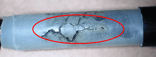
However, XLPE is very susceptible to treeing that is an electrical pre-breakdown phenomenon in solid insulation caused by partial discharge that progresses through the stressed dielectric insulation, in a path resembling the branches of a tree, as shown in Figure 1.

Treeing in a XLPE insulated cable

Figure 1 – Treeing in a XLPE insulated cable

Partial discharges are among the principal causes of catastrophic failures in cable terminations and joints. Main causes of discharges are deterioration of the insulation wall and joint defects.

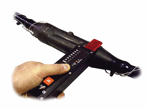
Acoustic Emission techniques can be used for the detection of partial discharges in cables and a Partial Discharge Scanner (PDS), like the one shown in Figure 2, may be used for partial discharges monitoring.

Partial discharge scanner

Figure 2 – Partial discharge scanner

Also Read: Cables Feeder Protection – Faults Types, Causes & Differential Protection

Treeing of solid medium and high voltage cable insulation is a common breakdown mechanism and source of faults in power cables.

Electrical treeing first occurs and propagates when a dry dielectric material is subjected to high and divergent electric field stress over a long period of time and it is observed to originate at points where impurities, gas voids, mechanical defects, or conducting projections cause excessive electrical field stress within small regions of the dielectric.

This can ionize gases within voids inside the bulk dielectric, creating small electrical discharges between the walls of the void. An impurity or defect may even result in the partial breakdown of the solid dielectric itself.

Over time, a partially conductive, branching 3D tree-like figure is formed within the dielectric. At first, the figure is microscopic in size, and is called a water tree.

The tree can grow to the point that it eventually causes complete electrical failure of the dielectric, at which point it is called an electrical tree.

This has been a long-term failure mechanism for buried polymer-insulated medium and high voltage power cables.

In a similar fashion, 2D trees can occur along the surface of a highly stressed dielectric, or across a dielectric surface that has been contaminated by dust or mineral salts. Over time, these partially conductive trails can grow until they cause complete failure of the dielectric.

Factors needed to be present in order for water trees to establish and grow in extruded cable insulation are:

  • Electrical field: Is usually the applied operating voltage on the cable; if no voltage is applied to the cable, no water trees will form.
  • Time: A relatively slow process, taking several years.
  • Existence of water or moisture substance.

The most important measure to prevent treeing in XLPE it is required end sealing of cables in storage, to avoid moisture to enter into the cable.

About the Author: Manuel Bolotinha

-Licentiate Degree in Electrical Engineering – Energy and Power Systems (1974 – Instituto Superior Técnico/University of Lisbon)
– Master Degree in Electrical and Computers Engineering (2017 – Faculdade de Ciências e Tecnologia/Nova University of Lisbon)
– Senior Consultant in Substations and Power Systems; Professional Instructor

The post Treeing in XLPE Insulated Medium & High Voltage Cables appeared first on Electrical Technology.


July 29, 2018 at 03:18AM by Department of EEE, ADBU: https://ift.tt/2AyIRVT

MV & HV Cable Termination to Equipment & Joints

9 topologies of medium voltage ring-main systems you should know about

Power systems are constructed can be operated as radial systems, ring-main systems or meshed systems. This technical article deals with nine most common topologies of ring-main systems, their characteristics and... Read more

The post 9 topologies of medium voltage ring-main systems you should know about appeared first on EEP - Electrical Engineering Portal.


View more at https://electrical-engineering-portal.com/mv-ring-main-systems
Credit- Electrical Engineering Portal. Published by Department of EEE, ADBU: tinyurl.com/eee-adbu

Current and voltage digital transformation in a modern substation protection and automation

Developments in communication have done much to realize the digital substation, but to realize a full digital substation it is necessary to have everything in digital form. Whilst much substation... Read more

The post Current and voltage digital transformation in a modern substation protection and automation appeared first on EEP - Electrical Engineering Portal.


View more at https://electrical-engineering-portal.com/current-voltage-digital-transformation
Credit- Electrical Engineering Portal. Published by Department of EEE, ADBU: tinyurl.com/eee-adbu

Installing and setting into operation of automatically controlled compensation banks

During previous decades manufacturers of automatic compensation banks faced increasing competition worldwide. They were forced to produce as economically as possible. Now, new technologies have been developed compared with the... Read more

The post Installing and setting into operation of automatically controlled compensation banks appeared first on EEP - Electrical Engineering Portal.


View more at https://electrical-engineering-portal.com/automatically-controlled-compensation-banks
Credit- Electrical Engineering Portal. Published by Department of EEE, ADBU: tinyurl.com/eee-adbu

How to create a specific neutral earthing system within existing one (islanding)

Each neutral earthing system has advantages and disadvantages for the safety of property, electromagnetic compatibility or continuity of service. The main system must therefore be chosen according to these criteria,... Read more

The post How to create a specific neutral earthing system within existing one (islanding) appeared first on EEP - Electrical Engineering Portal.


View more at https://electrical-engineering-portal.com/specific-neutral-earthing-system-islanding
Credit- Electrical Engineering Portal. Published by Department of EEE, ADBU: tinyurl.com/eee-adbu

Reasons and duties for switching in power transmission and distribution systems

The purpose of a power system is to transport and distribute the electric energy generated in the power plants to the consumers in a safe and reliable way. Generators take... Read more

The post Reasons and duties for switching in power transmission and distribution systems appeared first on EEP - Electrical Engineering Portal.


View more at https://electrical-engineering-portal.com/switching-power-systems
Credit- Electrical Engineering Portal. Published by Department of EEE, ADBU: tinyurl.com/eee-adbu

8 substation equipment needed to power up data center

A few years ago I participated in an interesting project Telenor Data Center in Belgrade – The most advanced technical building in the region of Central and Eastern Europe. The... Read more

The post 8 substation equipment needed to power up data center appeared first on EEP - Electrical Engineering Portal.


View more at https://electrical-engineering-portal.com/substation-data-center
Credit- Electrical Engineering Portal. Published by Department of EEE, ADBU: tinyurl.com/eee-adbu

Why to automate power substation? What do you get?

Substation automation involves the deployment of substation and feeder operating functions and applications ranging from SCADA and alarm processing, to integrated volt-var control in order to optimize the management of... Read more

The post Why to automate power substation? What do you get? appeared first on EEP - Electrical Engineering Portal.


View more at https://electrical-engineering-portal.com/why-to-automate-power-substation
Credit- Electrical Engineering Portal. Published by Department of EEE, ADBU: tinyurl.com/eee-adbu

Using full potential of IEC 61850 with these 2 functions for digital substation automation

Since IEC 61850 was published as an international standard for communication in substations, the standard has found broad acceptance on the markets. In the first substations to use it, the... Read more

The post Using full potential of IEC 61850 with these 2 functions for digital substation automation appeared first on EEP - Electrical Engineering Portal.


View more at https://electrical-engineering-portal.com/iec-61850-digital-substation-automation
Credit- Electrical Engineering Portal. Published by Department of EEE, ADBU: tinyurl.com/eee-adbu

Selection of relay for incoming and outgoing feeders for MV and LV MCC switchgears

Selection of proper relay is one of the most important stages to have a reliable network. In this article, selection of relay for incoming and outgoing feeders for LV switchgears... Read more

The post Selection of relay for incoming and outgoing feeders for MV and LV MCC switchgears appeared first on EEP - Electrical Engineering Portal.


View more at https://electrical-engineering-portal.com/relay-selection-incoming-outgoing-feeders
Credit- Electrical Engineering Portal. Published by Department of EEE, ADBU: tinyurl.com/eee-adbu

Using full potential of IEC 61850 with these 2 functions for digital substation automation

Since IEC 61850 was published as an international standard for communication in substations, the standard has found broad acceptance on the markets. In the first substations to use it, the... Read more

The post Using full potential of IEC 61850 with these 2 functions for digital substation automation appeared first on EEP - Electrical Engineering Portal.


View more at http://electrical-engineering-portal.com/iec-61850-digital-substation-automation
Credit- Electrical Engineering Portal. Published by Department of EEE, ADBU: tinyurl.com/eee-adbu

Selection of relay for incoming and outgoing feeders for MV and LV MCC switchgears

Selection of proper relay is one of the most important stages to have a reliable network. In this article, selection of relay for incoming and outgoing feeders for LV switchgears... Read more

The post Selection of relay for incoming and outgoing feeders for MV and LV MCC switchgears appeared first on EEP - Electrical Engineering Portal.


View more at http://electrical-engineering-portal.com/relay-selection-incoming-outgoing-feeders
Credit- Electrical Engineering Portal. Published by Department of EEE, ADBU: tinyurl.com/eee-adbu

What is Fixture’s Beam Angle & Beam Diameter (Part-2)

How to Measure Beam Diameter at Floor:

  • If we install lights at a certain height then how much light will be on the surface will be calculated by following equation.
  • Diameter of light Speared on Floor = 0.018 × Beam angle × The distance
  • For example if we need to calculate the diameter of light for a spotlight of 14° at 3 meter distance.
  • Diameter of Light Spread on Floor=0.018×14×3=0.756
  • As light moves away from a light source, it spreads out and becomes less intense.
  • The beam spread chart below gives a quick reference for common light angles and distances.

Beam Spread at various Beam angle and distance

Beam Angle At 5 Feet At 10 Feet At 15 Feet At 20 Feet
10° 0.9 feet 1.8 feet 2.7 feet 3.6 feet
15° 1.35 feet 2.7 feet 4.05 feet 5.4 feet
20° 1.8 feet 3.6 feet 5.4 feet 7.2 feet
25° 2.25 feet 4.5 feet 6.75 feet 9 feet
40° 3.6 feet 7.2 feet 10.8 feet 14.4 feet
60° 5.4 feet 10.8 feet 16.2 feet 21.6 feet
90° 8.1 feet 16.2 feet 24.3 feet 32.4 feet
120° 10.8 feet 21.6 feet 32.4 feet 43.2 feet

Lamp has Same Lumen but Different Lux due to change in Beam Angle:

  • Amount of Lux at Floor is depending upon Distance between lamp and working floor and Beam Angle of Lamp.

1

  • If the Lumens and distance between working plan and lamp is the same for all the four lights having beam angle of 10°,28°,38° and 60°.
  • The amount of Lux at working plan is different. At narrow beam angle 10° it is more Lux at the center of Light (1390 Lux) and it will be reduce as we move from the center. While for wide angle 60° it is less Lux at the Center (39 Lux).

Narrow Beam Angle have Good Light (Lux) at Central

  • A LED light bulb with a narrower beam angle may also seem brighter but the overall total luminous flux (Lumen) will be the same as the same LED light bulb with a lens which produces a wider beam angle. The brighter light is created by focusing the light within a more localized area, much like a magnifying glass can be used to focus the light of the sun. This is sometimes referred to the angular intensity of the light. 
  • If we use a narrower beam angle, we will increase light intensity but reduce the size of the area being illuminated for the same height.
  • The 10 degree beam will be brightest in the center; however, the lux drops very fast away from the center. Thus, it totally is wrong to conclude that 10 degree beam is brighter than the 60 degree beam and hence10 degree beam is a better light.
  • The 60 degree beam has low center lux because it has more light spread over a larger area. The 10 degree beam is good to provide spot lighting. The 60 degree beam may be good for different lighting ambiance.

Illumination as per Distance (Inverse Square Law of Illumination):

  • Only natural light provides even illumination on earth even though it pass from clouds, environment and shadows.
  • But all artificial light are affected from various factor and when the distance increases from the light source then the illuminance reduces according to distance.
  • This is phenomena is called the inverse square law of illumination where the illuminance falls to a quarter of its value if the distance is doubled.

2.jpg

  • As the luminous flux (Lumen) travels away from the light source the area over which it spreads increases, therefore the illuminance (lux) must decrease. The relationship is called as the inverse square law.
  • Illumination (E) = Lighting Intensity (Lumen) / (Distance)2
  • The inverse square law describes how the intensity of a light is inversely proportional to the square of the distance from the light source (the illuminator).
  • As light travels away from the point source it spreads both horizontally and vertically and therefore intensity decreases. In practice this means that if an object is moved from a given point, to a point double the distance from the light source it will receive only a ¼ of the light (2 times the distance squared = 4).
  • Taking this theory further, if an object at 10m from a light source receives 100 LUX, moving the object to 40m, it will receive only 1/16th of the light (4 times the distance, squared = 16) resulting in the object receiving only 6.25 LUX.


July 01, 2018 at 05:30PM by Department of EEE, ADBU: https://ift.tt/2AyIRVT