
Besides LoRa (acronym for long range) radios, there is another kind of radios that are already occupying the market segment with variety of applications, and that is Zigbee radios. Although Zigbee radios are substantially costly, they are in use due to their exceptional easy meshing capability. Zigbee radios can be placed in mesh configurations where every Zigbee is connected as a node with the others such that if one or many nodes fail, the network will still be functional!
Meshtastic is an open source project available on GitHub. Its LoRa network has a very long range and low power consumption, and is highly encrypted and immune to electromagnetic interferences. Author’s prototype is shown in Fig. 1
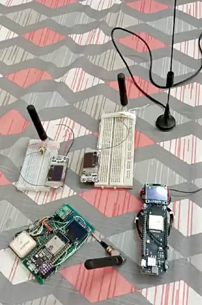
Meshtastic network
Meshtastic.org has introduced open source software to create the LoRa mesh network. LoRa works great on line of sight. Therefore, if one or two nodes can be placed at a strategically high place, all the nodes can talk to each other easily.
This is an attempt to create a practical mesh network for EFY readers where the sensor data, GPS position, and the triggering alarm can be operated with ease. The entire setup can be scaled up for bigger use.
Since this is not Arduino programming where the connections can be changed to required advantages, it needs to have fixed connections in line with Heltec LoRa-ESP32 right next to ESP32. Though this is not very difficult if the instructions are correctly followed, buying the ‘ESP32 Heltec LoRa’ from the market is also an option. The components used to make this device are listed in Bill of Materials table.
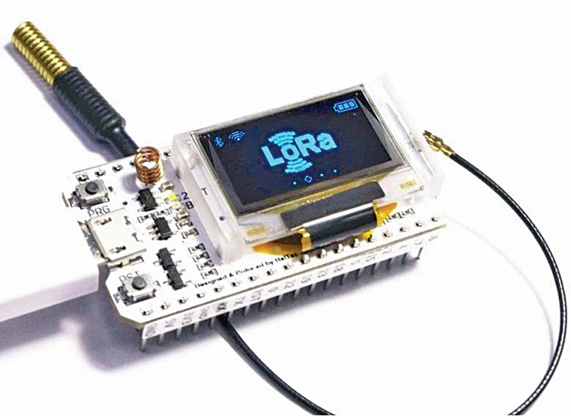
The Heltec LoRa module is also available from online stores at a higher cost. However, if you dare to follow this DIY, it is possible to build a handmade ESP32 Heltec LoRa module in less than ₹1500. You will need to procure some items first—an ESP32 development module, a 2.4cm (0.96-inch) OLED, an SX1278 868MHz SPI LoRa radio. Fig. 2 shows the Heltec LoRa module.
| Bill of Materials | |
| Items | Quantity |
| Heltec ESP32 LoRa/ESP32 MCU (MOD2) | 3 |
| HT7333A – 3.3V regulator (IC1) | 1 |
| SX1278 SPI LoRa (MOD1) | 3 |
| BME280 (MOD4) | 1 |
| MCP9808 – I2C OLED (MOD3) | 1 |
| SW1 | 1 |
| uBLOX GPS sensor with ANT.1 | 1 |
| 5V battery/adaptor | 1 |
Construction
To make a workable mesh network for testing, you need to have three or more LoRa nodes built as per the schematic, or purchase readymade ESP32 Heltec LoRa board from the market. At least one I2C sensor from the list is to be procured (BME280, BME680, MCP9808, INA260, INA219, SHTC3, SHT31, PMSA0031).
Now, to flush each ESP32 board with Meshtastic software, connect the board to the USB terminal of your computer and go to https://ift.tt/HzRkuyc. This link works only in Chrome or Edge browser.

The circuit diagram of the LoRa project is shown in Fig. 3. It is built around SX1278 SPI LoRa radio (MOD1), ESP32 development board (MOD2), I2C OLED (MOD3), BME280 (MOD4), 3.3V HT7333A regulator (IC1), and a few other components.
Flashing firmware
In the first screen, select the firmware version you want to flush with (Heltec V1). In the next screen, select the CP2102 USB to UART bridge, which is the interface hardware that sits in between the MCU and the computer. Next, follow the instructions that appear on the screen—like warning for erasing the entire device, etc.

Ensure the internet connection is stable during this crucial 4 to 5 minutes duration. For the built-in Heltec board you may need to keep the ‘Boot’ button pressed for the entire 4 to 5 minutes of the uploading phase.
Uploading software
By command-line-instruction method, you find that the browser-based firmware updation does not work reliably. Many times, it shows that it has completed the task very quickly, but it has not. It takes about 4 to 5 minutes time for installing/updating the firmware. That is why both the firmware and the command-line-instruction methods are provided here.
Mac commands/Linux commands
pip3 install --upgrade esptool [upgrade esptool first]
esptool.py chip_id [you will get a long output with chip id and chip mac id]
cd ~/Downloads/firmware/ [firmware-heltec-v1-2.2.12.092e6f2.bin]
./device-install.sh -f firmware-BOARD-VERSION.bin [for installing]
./device-update.sh -f firmware-BOARD-VERSION.bin [for updating]
Windows commands
device-install.bat -f firmware-BOARD-VERSION.bin (for installing)
device-update.bat -f firmware-BOARD-VERSION.bin(for updating)
Testing
To set up and test the project, you need to install Meshtastic app in your Android/iPhone (or tablet). There are Android and iOS versions available in their respective software stores (Google’s Play Store/Apple’s App Store). To work with the three nodes, fix one mobile phone (or tablet) to play with each node. That way many setup jolts would be avoidable. The app is free! Fig. 5 shows the Meshtastic icon.
First, power on the Heltec board. Next, switch on Bluetooth in your mobile phone and pair with the Heltec board. The 6-digit pairing number will appear on the OLED screen. After successful pairing, open the Meshtastic app and you will find the app is connected [look for the tick mark on top right] with the board’s Mac address. You can set a name for the board in the radio-configuration by pressing on the three dots (…) on right top of the app, as shown in Fig. 6.

The homemade Heltec is up now. Name it ‘fabr’ (short for fabricated one). The other two are not up. That is why question marks appear against their names. The tick mark on the top right cloud indicates that this node is connected.
Attaching sensors
Right now, only I2C sensors (on addresses 0x76, 0x77, 0x78, 0x18, 0x40, 0x41, 0x5D, 0x5c, 0x70, 0x44, 0x12, 0x3c are fixed for OLED) are allowed. More sensors will be added in the coming days. The Radio-configuration→Detection Sensor→Detection Sensor should be enabled.
You may provide a name to the sensor (BME or Temp_Ind). In the same window you can also designate a GPIO pin to monitor for [high or low] and the detection will be monitored periodically every 900 seconds (default value). Please note this GPIO pin status is totally independent of the sensor value. Fig. 7 shows the APP UI showing environment matrix log.

In Radio Configuration→Device →Role (for transmitting sensor value), name it ‘SENSOR’. The other options are ‘CLIENT’ or ‘ROUTER_CLIENT,’ ‘REPEATER’ etc. Fig. 8 shows the APP UI showing devices in Mesh.
To send signals to remote hardware, you must define the GPIO pin first. However, only digital read and digital write is enabled here.
External notifications
For external notifications, go to Radio Configuration→External Notification→Enable. You also must set the output GPIO pins which will receive the notifications. You can set LED/Alarm Buzzer/Alarm Vibrator on three different GPIO pins along with time duration of the alarm.
In the demo ‘fab’ unit the alarm on GPIO-16 is set to light an LED for two seconds. The sensor values will appear on the Android/iOS screen and on the OLED screen. To add a new node, just set the node up and it will be added in the network very easily.
GPS location
If the board has GPS locator, it will deliver it automatically. Otherwise, if the Android/iOS device has location information turned on, it will deliver the GPS location, which will be visible against that node in the app-window. The app has the facility to attach a separate GPS sensor, for which you must manually set the GPIO pins for Tx and Rx: Radio configuration→Position. (Refer Fig. 8, where location is coming from the phone location service.) However, after setting the GPS sensor, the location data (latitude and longitude) would come from GPS sensor.

As per the site, only uBLOX, GLONASS GPS sensors are supported at this moment. Author’s old GPS sensor (V.KEL TTL GPS sensor) also worked when connected.
Network
The network can be switched on by clicking Radio Configuration→Network→Enable
Wi-Fi→enter SSID and PSK. But doing this will make your node inaccessible by Bluetooth. Then you must access it by USB cable or network protocol using web server, which is not very friendly. Doing a reversal of this is very frustrating. You have to reinstall the firmware again!
Typical uses
In a forest area, LoRa mesh can be used to monitor forest fires. In such cases, each node will monitor air temperature, velocity, and humidity of its zone. In an industrial area, such mesh can be used very effectively for monitoring fire hazards. In a city, by turning vehicles to LoRa nodes, the vehicles’ speeds and positions can be monitored. In a township /housing complex, using V53LOX laser sensors, all the water tank levels can be monitored. It is possible to chat with the nodes and, using MQTT, it is even possible to reach other cities through Meshtastic LoRa networking.

Radio configuration→Module configuration→Store & Forward command works for ESP32 only. Here you can store a few records in the event of disconnection from node. However, Meshtastic does not recommend its use, normally.


Aftermath
The Meshtastic software has shown how a LoRa mesh can deploy the LoRa radios to get the best of networking for all good things like low power, great ranges, and impregnability. It’s fun to play with the network. After setting up the nodes, one can disconnect the Android/iOS devices, and the nodes will continue to work automatically.
Fig. 9 shows how an LED alarm fires up. Fig. 10 shows a mesh node device along with its sensor. The final prototype that includes ESP32, LoRa, OLED screen, and BME 280 sensor is shown in Fig. 11.
Somnath Bera is an electronics enthusiast. He is a freelancer and has contributed several articles across the globe
The post Meshtastic Network Of Inexpensive LoRa Radios appeared first on Electronics For You.
View more at https://www.electronicsforu.com/electronics-projects/meshtastic-network-lora-radios.
Credit- EFY. Distributed by Department of EEE, ADBU: https://tinyurl.com/eee-adbu
Curated by Jesif Ahmed