
Consider this digital stopwatch with dual timers if you are seeking a dual stopwatch that allows you to measure two distinct time intervals. It features two independent displays, which can be selected using the mode change switch. Here is a general guide on using this dual stopwatch:
1. Start/stop functionality: Most dual stopwatches have separate buttons to start and stop each timer independently. In this stopwatch, you also press the ‘Start’ button for each timer to initiate time measurement and release the same switch to stop the stopwatch. (Here we use push-to-on switches S1 and S2.)
2. Mode change functionality: Some stopwatches have a mode change function that allows them to change time in either seconds or milliseconds. This flexibility proves beneficial in various sports and activities. (Here we use a single-pole and double-throw (SPDT) switch S3.)
3. Reset: There is a reset switch to reset each timer when a time has already been displayed, setting the timers back to zero. (Here we use push-to-on switch S4.)
4. Display: This dual stopwatch uses a 3-digit display to show the elapsed time for each timer up to three digits. This allows measuring time in increments of 100 milliseconds or 100 seconds, utilizing three common cathode display (LTS 543)—DIS-1 through DIS-3.
When selecting a dual stopwatch commonly available in sports equipment stores or with online retailers, look for features such as precision, durability, and ease of use. The presented dual stopwatch provides precision to count up to 100 milliseconds and 100 seconds, making it suitable for specific applications.
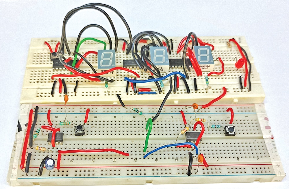
The author’s prototype on the breadboard is shown in Fig. 1.
Dual Stopwatch Circuit and Working
The circuit diagram of the dual stopwatch is shown in Fig. 2. It is built around two NE555 timers (IC1, IC2), three 4033 7-segment display drivers (IC3 through IC5), three common cathode 7-segment displays (DIS-1 through DIS-3), and several other components.
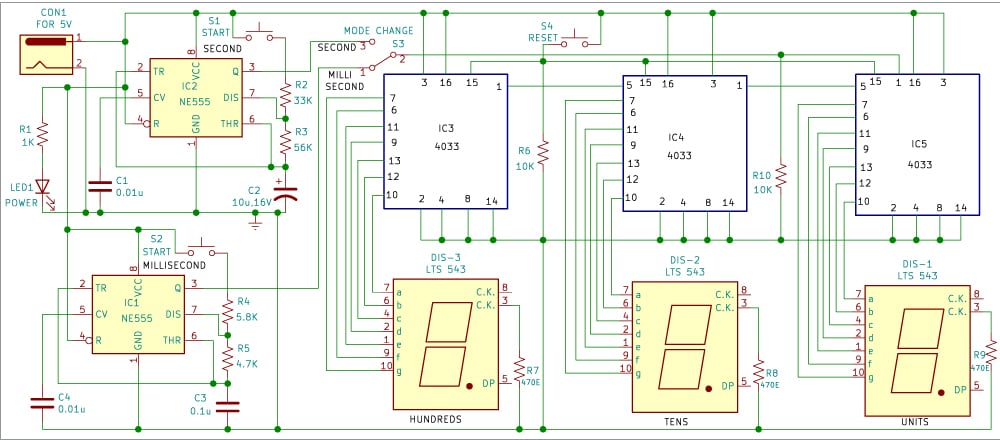
The 4033 IC facilitates easy interfacing with 7-segment displays and is versatile for applications like decade counting, seven-segment decimal displays, watches, and timers.
Timers IC1 and IC2 operate in an astable multivibrator mode, generating millisecond and second pulses, respectively. The outputs of these timers are routed to the three 4033 ICs (IC3 through IC5) to display units, tens, and hundreds of digits.
| Parts List | |
| Semiconductors: | |
| IC1, IC2 | – NE555 timer |
| IC3-IC5 | – 4033 decade counter |
| DIS-1-DIS-3 | – LTS543 common cathode 7-segement display |
| LED1 | – 5mm red LED |
| Resistors (all 1/4-watt, ±5% carbon): | |
| R1 | -1-kilo-ohm |
| R2 | -33-kilo-ohm |
| R3 | -56-kilo-ohm |
| R4 | -5.8-kilo-ohm |
| R5 | -4.7-kilo-ohm |
| R6 | -10-kilo-ohm |
| R7-R9 | -470-ohm |
| Capacitors: | |
| C1-C4 | – 0.01μF ceramic disk |
| C2 | – 10μF, 16V electrolytic |
| C3 | – 0.1μF ceramic disk |
| Miscellaneous: | |
| CON1 | – DC socket |
| S1, S2, S4 | – Push-to-on switch |
| S3 | – SPDT switch |
| – 5V DC adaptor | |
Switches S1 and S2 initiate and stop the stopwatch for milliseconds and seconds, Switch S3 enables mode change, and Switch S4 resets the stopwatch. A 5V DC socket powers the entire circuit, with LED1 indicating power presence.
In this stopwatch circuit, the delay in seconds is generated using IC2, and the duration of the delay is based on the value of the resistor used. The calculation formula for generating frequency for the astable multivibrator (built around IC2) is:
F=1/T=1.44/(R2+2R3) C2
Here R2 is 33k, R3 is 56k, and C2 is 10µF.
Similarly, astable multivibrator IC1 generates millisecond delays. The stopwatch operates by triggering the 7-segment decoder 4033 with pulses from the astable multivibrators.
The working of the stopwatch is straightforward. To illustrate, if you want to measure 50 seconds, set S3 to the seconds position, press reset switch S4, displaying 000. Press start switch S1 until the display shows 050, then release switch S1 to stop counting.
For measuring 500 milliseconds, follow a similar process with S3 in the millisecond position, pressing reset switch S4, displaying 000. Press start switch S2 until the display shows 500, then release S2 to stop counting.
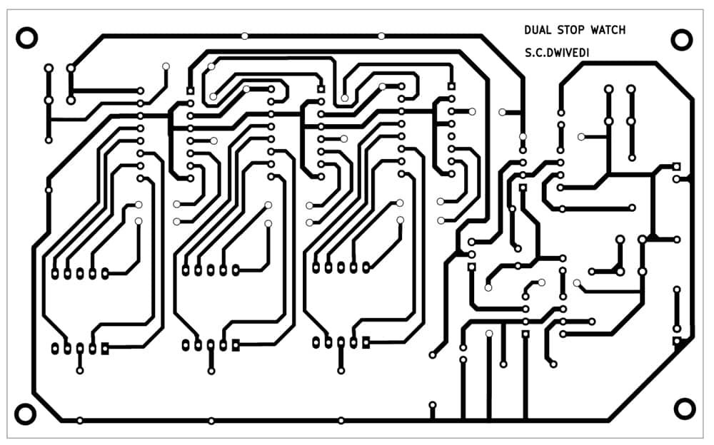
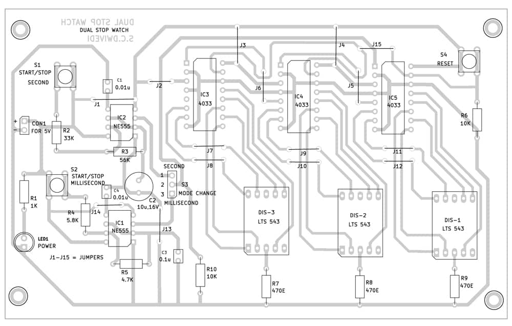
PCB Design
An actual-size, single-sided PCB layout for the dual stopwatch is shown in Fig. 3, with the component layout in Fig. 4. After assembling the circuit on the PCB, enclose it in a suitable box, placing LED1 and CON1 on the front side. Position the PCB to allow easy viewing of the three 7-segment displays for time reading. Fix switches S1 through S4 on the front or upper side for convenient access.
LED1 should illuminate upon connecting a 5V adaptor across CON1, indicating the dual stopwatch is ready for use.
Bonus. You can watch the video of the tutorial of this DIY project at: https://ift.tt/KnULbxw
S.C. Dwivedi is an electronics enthusiast and circuit designer at EFY
The post DIY Digital Dual Stopwatch appeared first on Electronics For You.
View more at https://www.electronicsforu.com/electronics-projects/diy-dual-stopwatch.
Credit- EFY. Distributed by Department of EEE, ADBU: https://tinyurl.com/eee-adbu
Curated by Jesif Ahmed