Types of Digital Asynchronous Counter (Ripple Counter)
What is Counter ?
A digital binary counter is a device used for counting binary numbers. Digital counters mainly use flip-flops and some combinational circuits for special features.
What is Asynchronous Counter or Ripple Counter?
The counter in which external clock is only given to the first Flip-flop & the succeeding Flip-flops are clocked by the output of the preceding flip-flop is called asynchronous counter or ripple counter. The name ripple counter is because the clock signal ripples its way from the first stage of Flip-flops to the last stage.
Types of Asynchronous Counters
There are two types of counters.
Synchronous counters and Asynchronous Counters. The asynchronous counter has many types. Some of them are given below.
- Up-Counter
- Down Counter
- Ripple Up/Down Counter
- Ripple BCD Counter
Up-Counter
Ripple up-counter starts counting from 0 and counts up to its maximum range. Its range depends on the number of flip-flop being used.
Ripple up-counter can be made using T-Flip flop and D-Flip flop.Designing of counters using flip-flops differs from each other with the type of flip-flop being used.
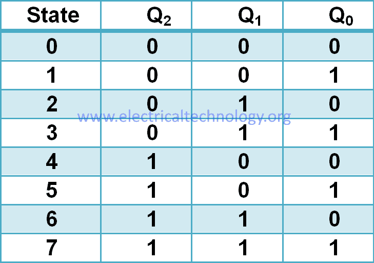
Consider a 3-bit counter with Q0, Q1, Q2 as the output of Flip-flops FF0, FF1, FF2 respectively. The state table for the 3-bit counter is given below:
Design Using T-Flip Flop
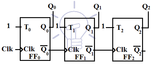
T-Flip flop toggles its state when its input T = 1. In Ripple counter using T-flip flop, input to all stages (flip-flop) is T = 1. The only thing which is not common in these stages is the clock signal. It means that the flip-flop will only toggle when the clock pulse hits the flip-flop. So the clock signal of the succeeding T-Flip flops has to be managed in such way that the Flip-flop toggles when they are supposed to.
Suppose positive edge sensitive T-flip flop is being used in the design.According to the state table of up-counter,
Q0 is toggling continuously so the external clock will be fed to the flip-flop FF0. It will toggle the Q0 upon the positive edge of the clock signal.
Q1 toggles when Q0 goes from 1 to 0. It means that the Negative edge of Q0 toggles Q1. So we can use Q0 as the clock input for FF1. We are using Positive edge triggered flip-flops so we will use complemented Q0 as the clock input for FF1.
Q2 toggles when Q1 goes from 1 to 0 (negative edge). This can also be used as a clock signal for FF2.Since we are using positive edge sensitive flip-flops, we need the complemented Q1 as the clock input for FF2
Schematic of ripple Up-counter using T-flip flop is given in the figure below.
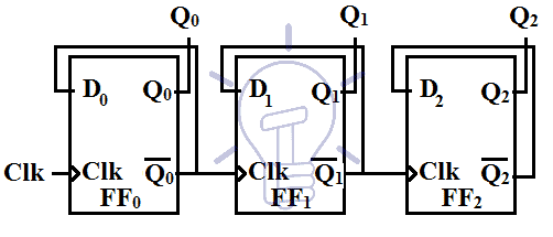
Design Using D-Flip Flop
Data or D-flip flop uploads input D as its output state Q upon clock edge. i.e Q = D. D-flip flop can also be used to implement Ripple Up-counter.
D-flop flop can be set to toggle its state upon the clock edge if its complemented output is feedback to its input. In such setup, D-flip flop can act as a T-flip flop with input T = 1.
Since the D-flip flop can be set to act as a T-flip flop, we can use the same design of T-flip flop up counter by replacing T-flip flop with D-flip flop. The input of each individual D-flip flop will be connected its complemented output D = Q̅. Whenever the clock edge hits the flip-flop will toggle its state.
The toggling pattern is the same as in the T-flip flop’s up-counter. So the clock signal input should be designed as in the T-flip flop Up-counter.
The schematic of Ripple up-counter using D-flip flop is given in the figure below:
Down Counter
This counter counts down numbers from highest possible count to 0 and then resets back from the highest count.
Assume 3 bit down counter with Q0 Q1 Q2 as outputs of flip-flops FF0 FF1 FF2 respectively. The state table of down-counter is given below:
Design Using T-Flip Flop
Designing of Down-counter is the same as up counter. The only difference is the toggling of the flip-flop. Each flip-flop toggles when its preceding flip-flop’s output goes from 0 to 1. It is opposite of the up-counter.
In up-counter, we used Positive edge sensitive flip-flops and we used Q̅ of preceding flip-flop as the clock signal for these flip-flops. In down-counter case we will use Q as the clock signal.
The schematic for Down-counter using T-flip flop is given below.
Design Using D-flip Flop
Design of Down-counter using D-flip flop is also same as T-flip flop down-counter. The clock signal that is provided to the succeeding Flip-flops in D-flip flop Up-counter will be changed as done in T-flip flop down-counter.
The output of each flip-flop will be fed as a clock input to the succeeding D-flip flops. This will enable the counter to count backward.
The schematic design for ripple down-counter using D-flip flop is given below:
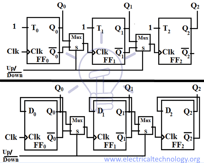
Ripple Up/Down Counter
This counter can do both up counting and down counting depending on the mode select switch. Mode select is a switch that selects between up-counting & down-counting. When M=1, the counter will count up and when M=0, the counter will count down.
The difference between the up-counter and down-counter is the clock signal. So we will use 2_1 Mux to select the 2 clock signals.
Schematic of ripple Up/Down counter is given below:
Ripple BCD Counter
BCD (Binary coded decimal) counter is a decade counter which has Mod = 10. Mod means the number of states the counter have. BCD counter counts decimal numbers from 0 to 9 and resets back to default 0. With each clock pulse, the counter counts up a decimal number.
Ripple BCD counter is same as Ripple Up-counter, the only difference is when BCD counter reached to count 10 it resets its flip-flops.
Consider Q0, Q1, Q2, Q3as 4 bits of the counter than the state table for Ripple BCD counter will be.
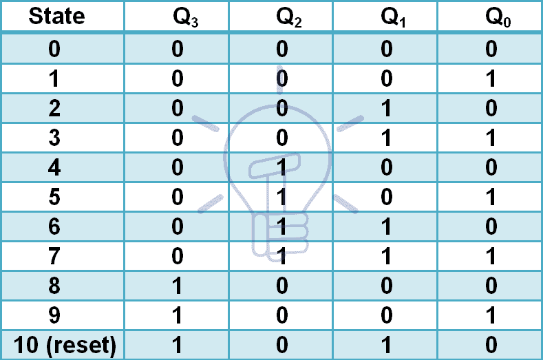
According to the state table, it is a simple up counter except state 10 as reset state condition.
Whenever the count reaches to state 10 the counter should automatically clear its flip-flops. For this purpose, we need a combinational circuit. Flip-flops have usually active-low clear. To clear all flip-flops the combinational circuit should produce logic ‘0’ when the counter reached state 1010. NAND gate also produces logic ‘0’ when all its inputs are true.
So we will use NAND gate to clear the flip-flop when it reaches to count 10.
Clear = (Q3 AND Q1)’
Ripple BCD counter can be made using T-flip flops or D-flip flops.
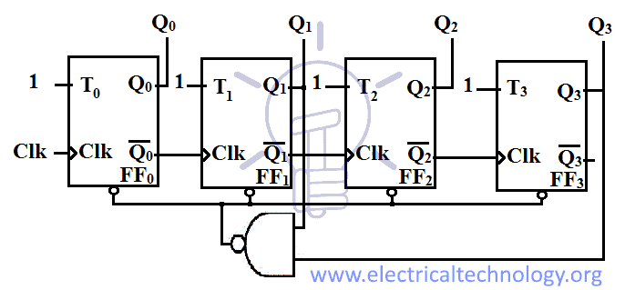
Design Using T-Flip Flop
We will use the reset condition for the up-counter T-flip flop to make it BCD counter. It schematic is shown in the figure given below:
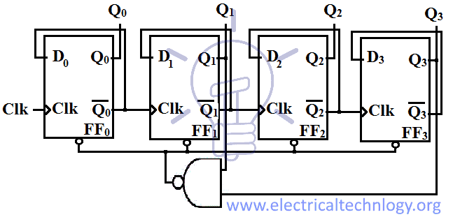
Design Using D-Flip Flop
We can modify the D-flip flop Up-counter into ripple BCD counter. Essentially these both are the same up counter but BCD counter has a limit of 10 counts. So when up-counter reaches count 10 it should reset to default state which makes it a ripple BCD counter.
Schematic for Ripple BCD counter using D-flip flop is given below:
Advantages of Asynchronous Counters
- It can be easily designed by D-flip flop or T-flip flop.
- It can be used in low speed circuits.
- It is used as Divide by-n counters.
- They are also used as Truncated counters. (to design any mod number counters, i.e. Mod 4, Mod 3).
Disadvantages
- For Re synchronization, extra flip flop are needed.
- Additional feedback logic is needed to count the sequence of truncated counters (keep in mind that mod is not equal to 2n).
- The propagation delay of asynchronous counters is very large, while counting large number of bits.
- Due to propagation delay, counting errors may occur for high clock frequencies.
- They are slower as compared to synchronous counters.
Applications of Asynchronous Counters
- They are used as frequency dividers, as divide by “N” counters.
- They are used for low noise emission and low power applications
- They are used in designing asynchronous decade counter.
- It is also used in Ring counter and Johnson counter.
- Asynchronous counters are used in Mod N ripple counters. i.e. Mod 3, Mod 4, Mod 8, Mod 14, Mod 10 etc.
You may also read:
- Digital Logic NOR Gate – Universal Gate
- Exclusive-NOR (XNOR) Digital Logic Gate
- Digital Logic AND Gate
- Digital Logic OR Gate
- Logic NOT Gate – Digital Inverter Logic Gate
The post Digital Asynchronous Counter (Ripple Counter) & Types appeared first on Electrical Technology.
May 07, 2018 at 02:08AM by Department of EEE, ADBU: https://ift.tt/2AyIRVT