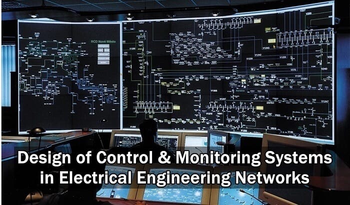
Design of Control & Monitoring Systems in Electrical Networks
Design Implementation
The preparation of the design of control and monitoring systems requires the definition of a set of actions:
- Definition of equipments and systems to be controlled and monitored (all equipments – circuit breakers, instrument transformers, isolators, switches, etc. – must be identified by a code, defined by the Construction Owner or by the designer, if no instructions exist.
- Definition of the type of control and monitoring to implement, according to the complexity of the installation.
- Definition of protections units to use, establishing the tripping matrix.
- Definition of the “set-points” of the protection units.
- Definition of interlocking matrix.
- Definition of operation sequences and sequential automatisms, if any.
- Synchronization of MV, HV and EHV (MV: Medium Voltage; 1 kV < V < 60 kV. HV: High Voltage; 60 kV ≤ V < 150 kV. EHV: Extra High Voltage; V ≥ 150 kV) circuit breakers (closing in the condition “live bar – live line”).
- Reclosing programme.
- Definition of digital and analogue input and output signals .
- Definition of general alarms and respective data treatment.
- Definition of electric parameters to be monitored and measured.
- Definition of time delays to be established.
- Definition of disturbances to be recorded.
- Establishment of switching programmes, under normal and emergency situations.
- Definition of operation sequences and sequential automatisms, if any.
- Load shedding, if required.
- Interactions between equipments and/or systems (local and remote).
- Events and respective data to be remotely transmitted.
- Control and monitoring input signal from the remote control center(s).
- General communication networks.
Documents to be Produced
Apart from single line diagrams of the global installation, showing all equipments and their codes and the protection units, it must be produced for each part of the installation and for each equipment to be controlled and monitored, the control and monitoring schematic diagrams, which are important pieces for maintenance and failures detection.
In these diagrams it must be represented all equipments to be controlled and monitored and control equipments, either manual or automatic (auxiliary relays, control switches, etc.), dully codified, interlocking (if any), as well as auxiliary contacts of protection units, pilot lights and metering equipment.
The above referred diagrams must be complemented by wiring diagrams of power and/or control switchgears, panels and cabinets, showing the respective terminal blocks, dully identified, with the connection of conductors of internal wiring and control cables. Each conductor must be identified with a label, defining the connection in accordance with was defined in the design documents.
A cable list must also be produced, showing:
- Type of cable, number of conductors and cross section.
- Cable origin and destination.
- Cable identification, according to was defined in the design documents.
- Cable routing.
Logic Diagrams & Operation Equations
Within the design of control and monitoring systems it must also be considered the programming instructions for microprocessed units of the system, which must include interlocking, tripping orders, equipment blocking situations and eventual sequential automatisms.
These instructions may be produced under as logic diagrams or operation equations.
a) Logic diagrams
Logic diagrams associated events (represented by capital letters) that traduce the conditions to be fulfilled to logic bloks of mathematic logical operations – logical conjunction (˄) and logical disjunction (˅).
It is assumed that an event A can have the following values:
- A = 1 – event verified.
- A = 0 – event not verified.
b) Operation equations
Operation equations use Boolean Algebra, establishing equations between the events (represented by capital letters), mathematic logical operations – logical conjunction (˄) and logical disjunction (˅) – to algebraic operations ( x ; + ).
For an event X it is assumed the following convention:
- X – event verified.
- X̅ – event not verified
Interlocking & Local Manual Control
In order to avoid wrong maneuvers that can damage the equipment and cause hazards to the employees an interlocking program must be implemented.
The most common wrong maneuvers in electrical installations are:
- Open or close isolators with the circuit breakers closed (on load manoeuvre).
- Close earthing switches with circuit breakers and/or isolators closed and with voltage present.
- Close circuit breakers and/or isolators with earthing switches closed.
- Close other circuit breakers when the protection relay 50BF is activated.
There are two types of interlocking: electrical and mechanical.
Electrical interlocking is intended to prevent non authorized electrical control and is performed through “hardware” (relays and cabling), through “software”, or a combination of both.
Mechanical interlocking is intended to prevent local manual control and can be achieved by padlocks and locks, or can be built-on, which is the case of isolators with earthing switches in substations.
Equipments can be provided with both electrical and mechanical interlocking.
Local manual control is performed close to the equipments. By safety reasons, this type of control, with the exception of emergency situations, is only possible to do when it is authorized by the person in charge of the operation of the electrical installation, which will get it “free” to be performed by a designated operator.
For manual control interlocking can only be superseded by personnel dully authorized:
“Hardware” interlocking: using control switches with key, which is only accessible to authorized personnel.
“Software” interlocking: using a “key word” that allows to supersede interlocking only to authorized personnel.
The post Design of Control & Monitoring Systems in Electrical Engineering appeared first on Electrical Technology.
July 30, 2018 at 05:50PM by Department of EEE, ADBU: https://ift.tt/2AyIRVT

