Digital Logic AND Gate

Digital Logic AND Gate

What is a Logic Gate?

A logic gate is used to implement Boolean function by performing a logical operation. It ta  kes binary logic as input and produces binary logic as an output.

A logic gate is basically the building block of a digital circuit. All the digital systems within the world are composed of logic gates.

Logic gates work on binary Logic refer as High-State “1” and Low-State “0”.

These gates have usually two inputs and one output. Combinations of Binary Logic Low ”0” and logic High ”1” is given as inputs to these logic gates, and their corresponding output is produced based on their Boolean functions.

Good to know:

These terms also used in binary logic gates and circuits

0 or 1

Low or High

True or False

ON or OFF

Basic And Derived Logic Gates

AND, OR, NOT, NAND, NOR are the basic logic gates. Basic gate combines together to form Derived logic gates like XOR, XNOR etc.

What is Logic AND Gate

AND Gate is a basic logic gate which provides High-State “1” once all of the inputs to the AND Gate are High-State”1”. If any of the input is Low-State ”0”, than its output is Low-State ”0” .It is also referred to as arithmetic multiply operation.AND gate - Digital logic AND Gate
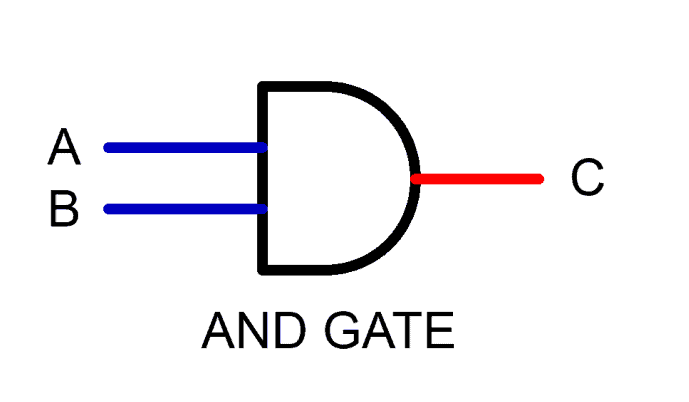
AND Gate Logic Symbol, Boolean Expression & Truth Table

AND Gate Symbol

There are 3 types of symbols used for AND gate all over the world

American National Standards Institute (ANSI)/ MILITARY
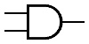
ANS MILITARY

International Electrotechnical Commission (IEC)/EUROPEAN
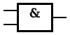
IEC EUROPEAN

Deutsches Institut für Normung (DIN)/GERMANY
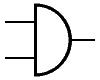
DIN GERMANY

Boolean Expression

C = A.B or C = A & B

Truth Table

A mathematical table used to specify input to output logic combination of a digital circuit is known as a truth table, the truth table of AND Gate is given below.
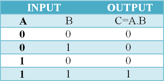
AND GATE Truth Table

AND Gate Logic Flow Schematic Diagram
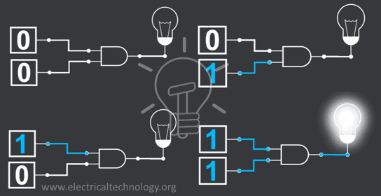
LOGIC FLOW SCHEMATIC

Construction and Working Mechanism of AND Gate:

AND Gate using Resistor-Diode Logic(RDL)

In Resistor-Diode Logic (RDL), the diode is used as a switch. In AND Gate, diodes are placed in such configuration when any of the two input is logic-Low “0”, the corresponding diode will become forward bias and logic-Low”0” will flow through output as there is no resistance in its path. When both inputs are logic-High”1” diodes will be reversed biased, Hence Vsupply (Logic High state) will be routed to output C as “1”.

NOTE: There is always diode forward voltage drop of approximately 0.7 volts in the case of silicon and 0.3 volts in the case of the germanium diode.
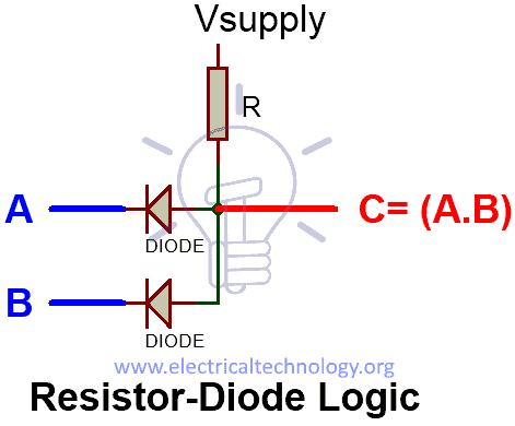
AND Gate using Resistor-Diode Logic(RDL)

AND Gate using Resistor-Transistor Logic (RTL)

In Resistor-Transistor Logic (RTL), the main switching unit is the transistor. In the figure given below, there are 2 NPN transistors connected in series that switches on with logic level high ”1”, when both of the transistors are turned on, Vcc”1” will flow through output. There is a pull-down resistor connected to the output, Therefore there will be always Logic-Low”0” at the output unless both of the transistors are switched on.

NOTE: RTL logic limitation or disadvantage is that it has high power dissipation due to current flow in base resistors and collector resistors when the BJT’s are switched on.
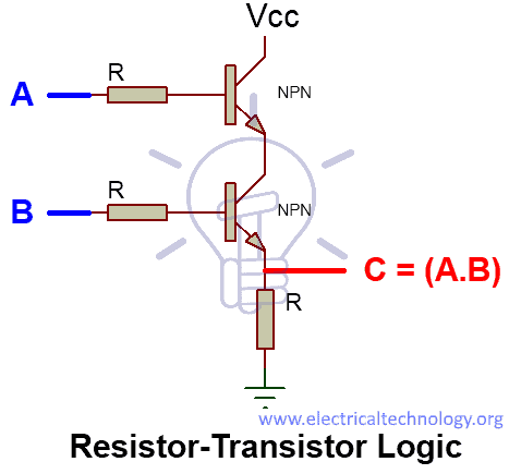
AND Gate using Resistor-Transistor Logic (RTL)

AND Gate using MOS Logic

In MOS Logic, MOSFETs are used as the main switching unit. As you can see in the figure below the two MOSFET in series are being controlled by the inputsignal, In turn, these NMOSFETs control the other NMOSFET. When both inputs are High-State”1”, the NMOS connected in series activates and successively,NMOS on the OUTPUT side is switched off due to logic low gate input (GND). Thus the only route to output is from Vdd (Logic high).

When any of this input is Low-State”0”, the NMOS connected in series will be switched-off resulting in High State”1” at the gate of NMOS on the OUTPUT side(Switched-on). As the NMOS is switched-on, therefore the output C will be directly connected to GND (Low State”0”).
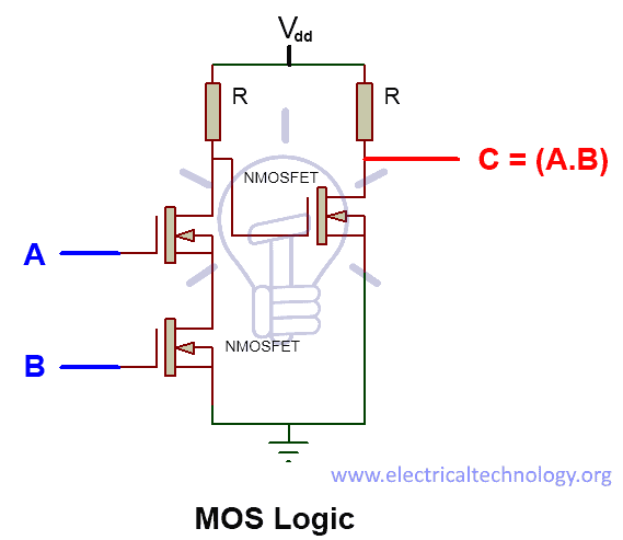
AND Gate using MOS Logic

AND Gate From Other Logic Gates

AND gate’s function can be achieved by different combinations of different logic gate some of them are given below.

BOOLEAN EXPRESSION:

AND Gate From NAND Gate

C = ((A.B)’)’
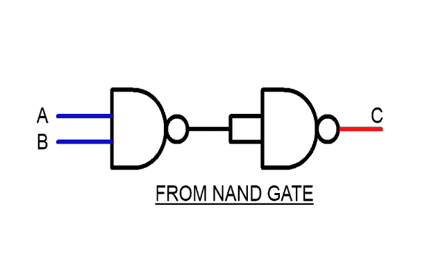
From NAND Gate

AND Gate From NOT-NOR Gate

C = A.B

C = (A’+B’)’

From NOT,NOR Gate

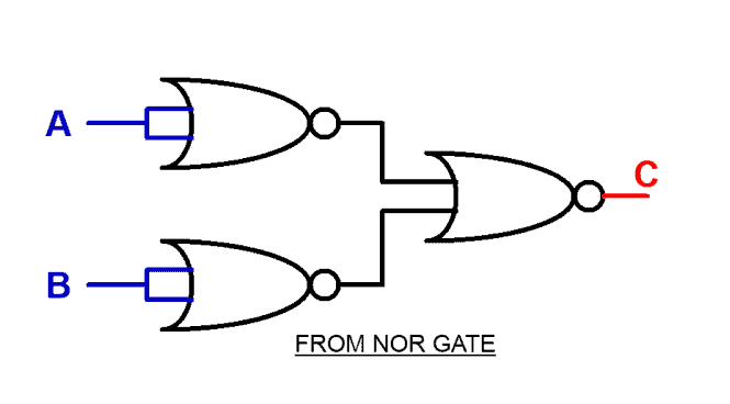
AND Gate From NOR GATE

C = (a’+b’)’

C = ((A+A)’ + (B+B)’)’From NOR GATE
Multiple Input AND Gate

As we have established before that AND Gate gives logic High State”1” only and only when all of its inputs are logic High State”1”. It’s“n” number of inputs truth table is given below:
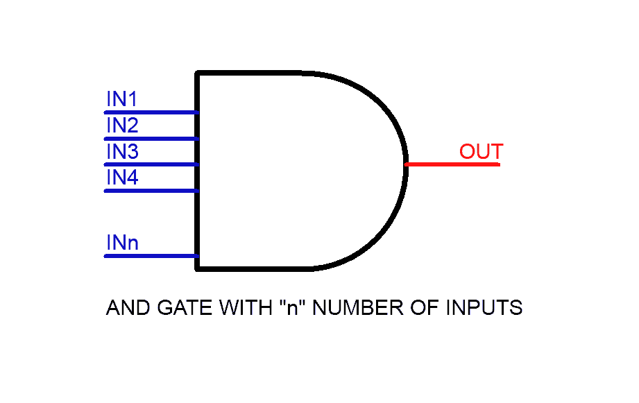
MULTIPLE INPUT AND GATE

Truth Table

NOTE: In the table given below “X” means “don’t care”. It can be “1”and it can be “0”. Which means, as long as there is a single input carrying “0”, the output will be always “0” so there is no reason to put a check on other inputs, that’s why it’s called “don’t care X”.
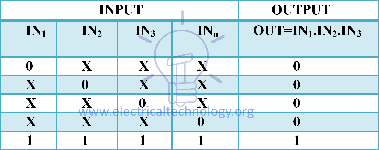
What would you do if there are more than two inputs needed? The answer is simple.

Resistor-Diode Logic

IN RDL (Resistor-Diode logic) logic, a diode is used on every input line, thus adding diodes can increase the number of input lines as shown in the figure below. Each input is fed to separate diode. Place as many diodes as you would like,to create a Multi-Input AND GATE.
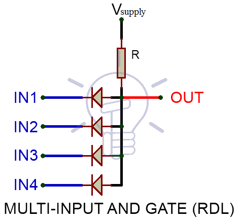
Multi-Input AND GATE RDL (Resistor-Diode logic)Resistor-Transistor Logic

In RTL (Resistor-Transistor Logic), Transistors are used as switching unit. To increase the input lines we have to increase the number of transistors connected in series as shown in the figure below.
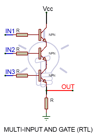
Resistor-Trasnsistor Logic RTL AND GateResistor-Trasnsistor Logic RTL

MOS Logic

In MOS logic, the case is same as RTL logic, instead, we increase the number of MOSFETs connected in series at the input side. AND GATE with three input in MOS logic is given below. If you want to add another input, add another NMOS in series.Multi input AND Gate MOS Logic

Cascaded Setup of AND Gates

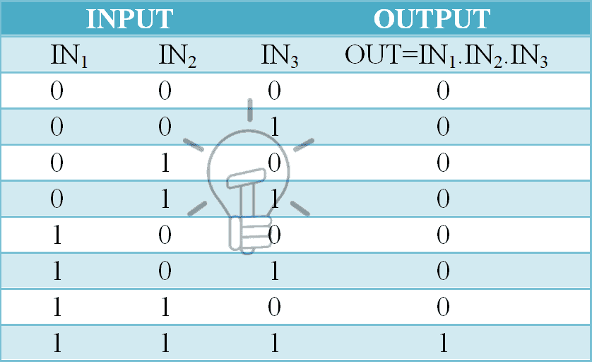
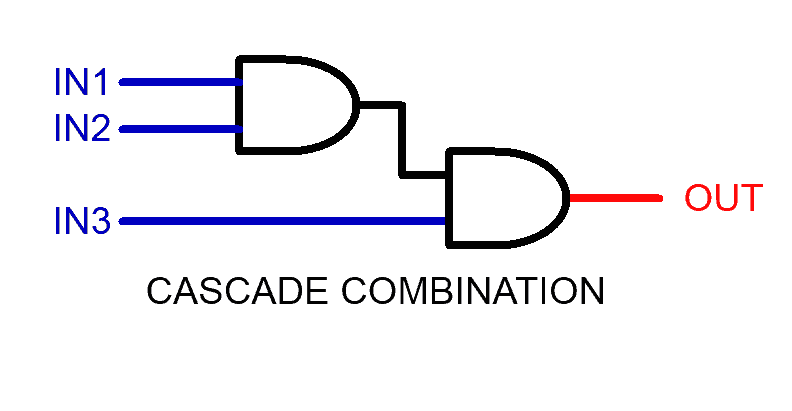
Multi-input AND gate function can be achieved by cascading Two-Input AND Gate in a specific configuration given below

OUT    =          IN1 & IN2 & IN3

OUT    =          (IN1 & IN2) & IN3Cascaded Setup of AND Gates
OUT    =          IN1 & IN2 & IN3 & IN4

OUT    =          (IN1 & IN2) & (IN3 & IN4)
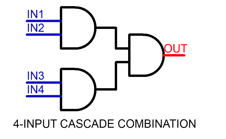
4 input cascade combination

TTL and CMOS Logic AND Gate IC’s

Commercially up to Four-Input AND gate IC’s are available in the market, having two AND gates in a single package. Some of the ICs with Pin Details are given below.

TTL Logic AND Gates

  • 74LS08 Quad 2-input
  • 74LS11 Triple 3-input
  • 74LS21 Dual 4-input

CMOS Logic AND Gates

  • CD4081 Quad 2-input
  • CD4073 Triple 3-input
  • CD4082 Dual 4-input

7408 TTL and 4081 CMOS AND Gate IC (Two-Inputs)
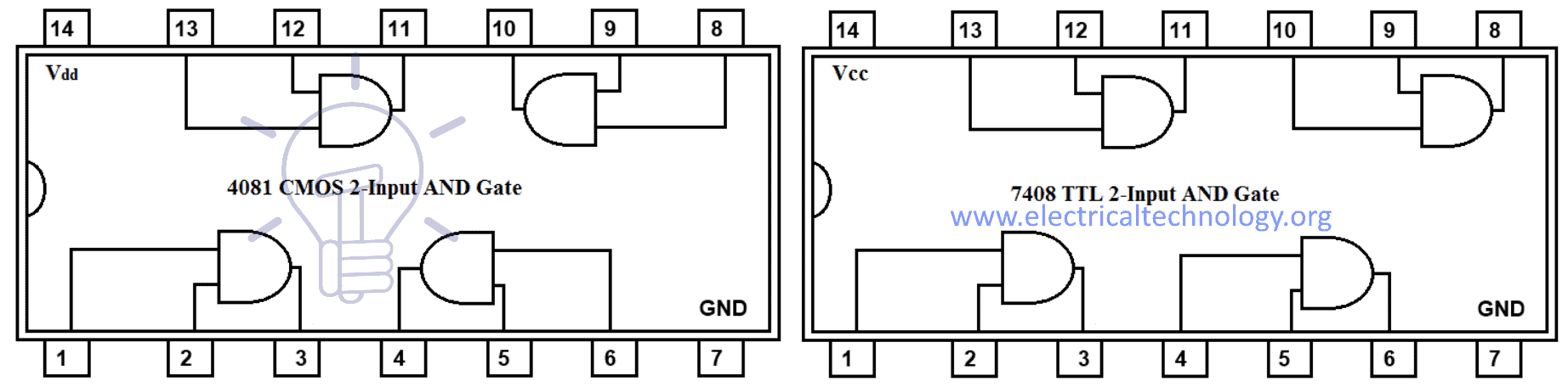
7408 TTL and 4081 CMOS AND Gate IC (Two-Inputs)

Pinout for 7408 TTL AND Gate IC

PIN Number Description
1 Input Gate 1
2 Input Gate 1
3 Output  Gate 1
4 Input Gate 2
5 Input Gate 2
6 Output Gate 2
7 Ground
8 Output Gate 3
9 Input Gate 3
10 Input Gate 3
11 Output Gate 4
12 Input Gate 4
13 Input Gate 4
14 Positive Supply Voltage

4073 CMOS and 7411 TTL AND Gate IC (Three-Inputs)
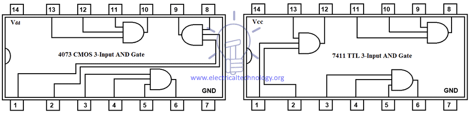
Three-Inputs IC

4082 CMOS and 7821 TTL AND Gate IC (Four-Inputs)
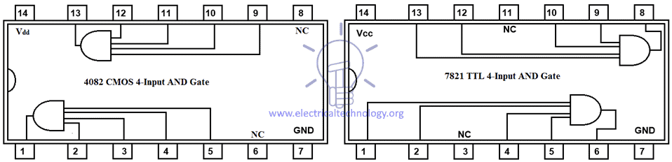
Four-Inputs IC

AND Gate Applications

Common uses and application of AND gate are follow:

  • As enable gate (Allowance of data through a channel).
  • As inhibit gate (Reverse of enable gate i.e. disallowance of data through a channel).
  • In the clock counters as enable and disable gate.
  • Used in security devices e.g security lights and flood lights as PIR (Passive infrared) Device.
  • In most of counting, computers and logic based digital circuits,

You may also read:

Digital Logic OR Gate Digital Logic NOT Gate

The post Digital Logic AND Gate appeared first on Electrical Technology.


April 14, 2018 at 02:43AM by Department of EEE, ADBU: https://ift.tt/2AyIRVT

Digital Logic OR Gate

Digital Logic OR Gate – Digital Gates

What is Logic OR Gate

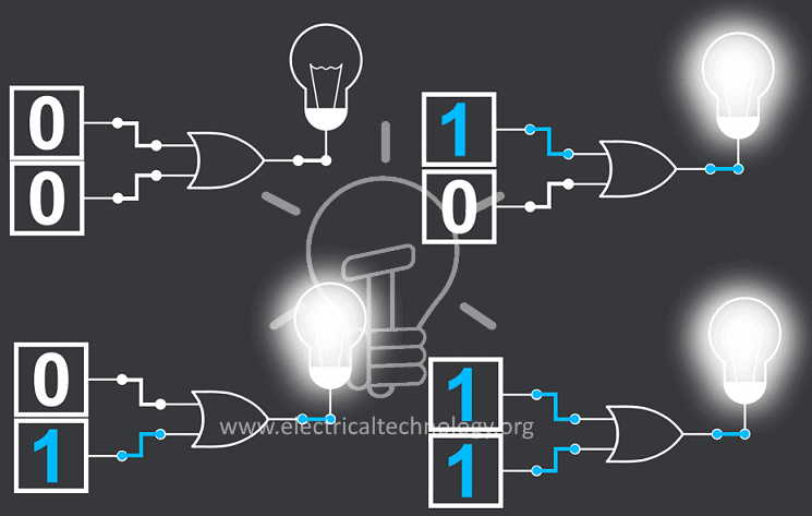
A logic gate which gives low state “0” only and only when all of the inputs are low state “0”. Otherwise, provide high state “1” as output.

Logical OR gate can have 2 or more than 2 input lines but it has one output line. It can be either true or false, true being High state”1” and false being Low state”0”.

LOGIC OR GATE

OR Gate works on submission bases. i.e.

If either “A” or “B” is “1”, Then “C” is 1.

Good to know:

These terms also used in binary logic gates and circuits

0 or 1

Low or High

True or False

ON or OFF

OR Gate Logic Symbol, Boolean Expression & Truth Table

OR Gate Symbol

There are 3 types of symbols used for OR gate all over the world.

American National Standards Institute (ANSI) MILITARY

American National Standards Institute (ANSI) MILITARY

International Electrotechnical Commission (IEC) EUROPEAN

International Electrotechnical Commission (IEC) EUROPEAN

Deutsches Institut für Normung (DIN) GERMANY

Deutsches Institut für Normung (DIN) GERMANY

Boolean Expression

In Boolean algebra (+) sign is used for OR operation, which gives high state “1” if either one or both of the operands are a high state. In most of the programming languages (|) is used for Bit wise OR operation while (||) is used for logical OR operation.

C = A+B,         C=A|B,            C=A || B,

Truth Table

A mathematical table used to specify input to output logic combination of a digital circuit is known as a truth table, the truth table of OR Gate is given below.

OR Gate truth table

OR Gate Logic Flow Schematic Diagram

OR Gate Logic Flow Schematic

Construction and Working Mechanism of OR Gate

OR Gate using Resistor – Diode Logic

In resistor-diode logic (RDL), the diode is used as a switching unit. In the schematic given below RDL logic OR gate is given, in which 2 diodes and 1 pull down resistor are used. Pull down resistor means that whenever the diodes are in reversed bias it will pull output voltages down to 0 volts (LOW state “0”).

Diodes are used in a parallel configuration. When both of the input A and B are “0”, diodes will be reverse bias meaning no current will flow; as a result, output volts will be pulled down i.e. LOW STATE “0”. And if there is even a single high state input, then its corresponding diode will become forward bias resulting in high state “1” flow out as output. Hence resulting in the truth table given below.

There is also 0.7 volts drop in the diode.OR Gate RESISTOR-DIODE LOGICOR Gate truth table

OR Gate using Resistor – Transistor Logic

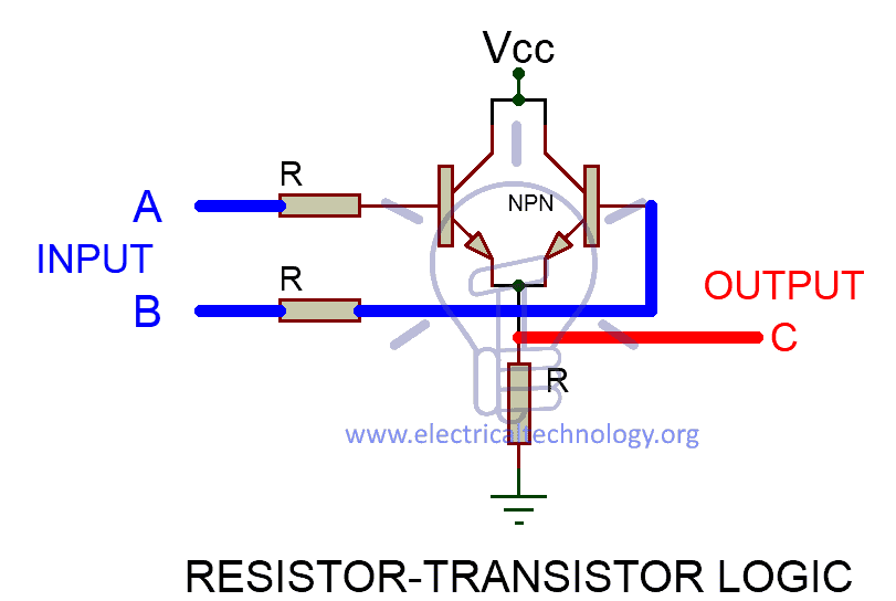
In Resistor-Transistor logic (RTL), Bipolar Junction Transistor (BJT) is used as a switching unit. BJTs are high power consumption devices as it operates on base current. RTL logic schematic of OR gate is given in the figure given below. In this schematic two NPN transistor is used in parallel configuration and 2 input resistors and a pull-down resistor.

There are two discrete input lines connected with separate NPN transistor’s base. And an output line is taken between resistor and NPN Transistors.

NPN transistors switch on when there is a HIGH input at its base and current starts flowing through the transistor.

When both of the inputs are LOW state “0”, BJTs will be switched off, as a result, there will be no current flow and OUTPUT “C” will be pulled down to “0 LOW state”.

When there is a single HIGH state input, one of the BJTs connected in parallel will turn on and start conducting current and eventually producing voltage Vcc “high state 1” across load resistor “R” which is taken as OUTPUT C.

The truth table of the described schematic is given below.RESISTOR-TRANSISTOR LOGIC logic schematic of OR gateOR Gate truth table

OR Gate using MOS Logic

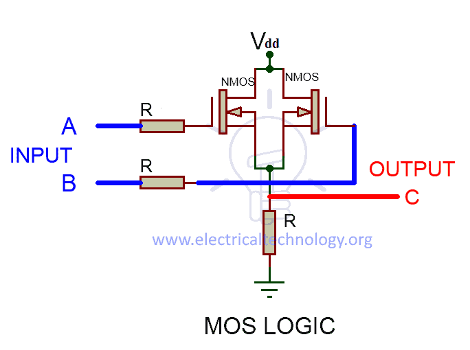
In MOS logic, the main switching units are MOSFETs, MOSFETs are fast switching, low power consumption devices as it operates on gate voltages, MOS logic schematic of OR gate is given in the figure below.

MOS logic uses the same working principle as RTL logic, the only difference is use MOSFETs instead of BJTs. As you can see in the figure given below inputs are fed through the input resistor to the gates of two parallel connected NMOSFETs and output is taken across load resistor “R1”.

NMOSFETs switch on when there is high state “1” on its gate and starts conducting current through it. And turns off when there is LOW state and become open(no flow of current).

When both input lines are LOW state “0”, both NMOSFETs will be switched off and there will be no current flow. So the only path connected to output will be GND (LOW state 0).

If there is a single high state input or both of the inputs are a high state then one or both of the NMOSFETs will be switched on respectively. It will give a closed path for current to flow through Vdd to GND. As a result, there will be a voltage drop across LOAD resistor resulting in HIGH state “1” at the output.MOS logic schematic of OR gateOR Gate truth table

OR Gate From Other Logic Gates

OR gate functionality can be achieved with the help different combinations of the different logic gate. Some of them are given below;

NAND and NOR gates are Universal gates which can be used to implement any kind of Boolean function. It’s very easy to implement,

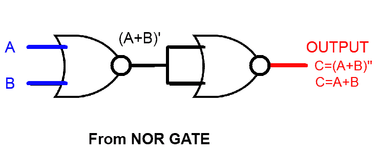
OR Gate constructed from NOR Gate

OR Gate from NAND Gate

OR Gate Function from NAND Gate

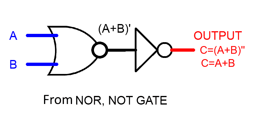
OR Gate from NOR, NOT Gate

OR gate constructed from NOR GATE is given above. NOR is actually INVERT of OR. So placing an INVERT/NOT gate to the output of NOR gate will provide OR gate’s result. Or placing a NOR gate with common input line in front of NOR gate will also do the job as it will act as an INVERTER.

NAND gates operation is same as AND gate but with an inverted output. So feeding it inverted input will provide the Operation OR as explained in below Boolean expressions

C = (A + B)              Taking complement on both side

C’= (A + B)’             De Morgan’s law

C’= (A’ . B’)             Taking complement again on both side

C= ( A’ . B’)’

OR Gate with Multiple Input

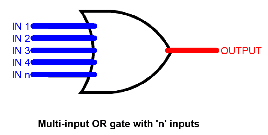
OR gate can have more than 2 inputs and can be used according to the requirements of the schematic design.

OR gate with “n” number of input is given below.

MULTIPLE INPUT OR GATE

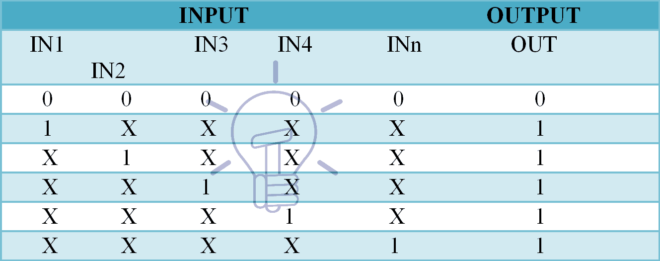
Truth Table

NOTE: In the table given below “X” means “don’t care”. It can be “1”and it can be “0”. Which means, as long as there is a single input carrying “1”, the output will be always “1” so there is no reason to put a check on other inputs, that’s why it’s called “don’t care X”.

MULTIPLE INPUT OR GATE Truth Table

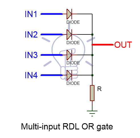
Resistor-Diode Logic

IN RDL (Resistor-Diode logic) logic, a diode is used on every input line, thus adding diodes can potentially increase the number of input lines as shown in the figure below. Each input is fed to separate diode. Place as many diodes as you would like, to create a Multi-Input RDL OR GATE.Multi-Input Resistor-diode logic OR GATE

Resistor-Transistor Logic

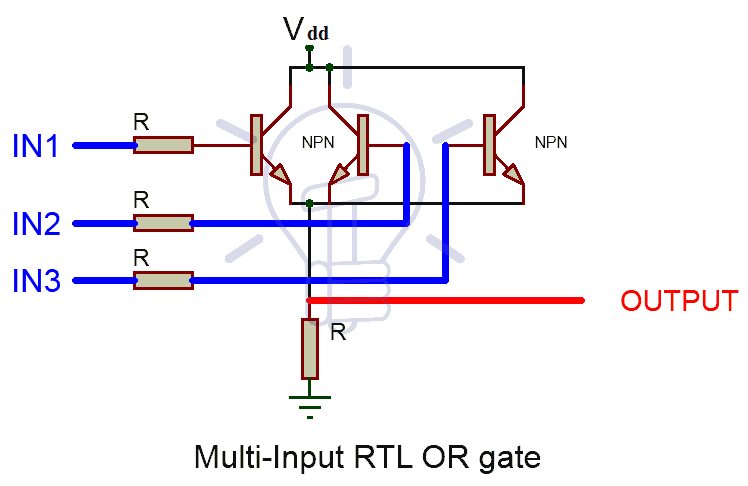
In RTL (Resistor-Transistor Logic), Transistors are used as switching unit. To increase the input lines we have to increase the number of transistors connected in parallel as shown in the figure below

Multi Input Resistor-Transistor Logic (RTL) OR Gate

MOS Logic

The idea to create a Multi-Input OR gate in MOS logic is exactly same as in RTL logic. Increasing the number of MOSFETs in parallel can potentially increase the number of input lines. The figure given below shows MOS logic OR gate schematic.

Multi Input Resistor-Transistor Logic (RTL) OR Gate

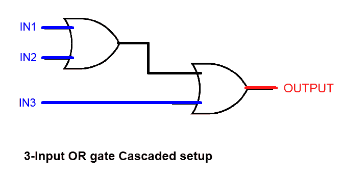
By Cascading 2-input gates

Multi-input OR gate can be made from cascading setup of 2-input OR gates as shown in the figure given below.

OUT                =             IN1 + IN2 + IN3

OUT                =          (IN1 + IN2) + IN3

3 input OR Gate cascaded setuo

OUT              =            IN1 + IN2 + IN3 + IN4

OUT                =          (IN1 + IN2) + (IN3 + IN4)4 input OR Gate cascaded setup

TTL and CMOS Logic OR Gate IC’s

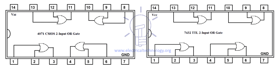
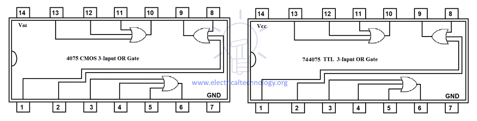
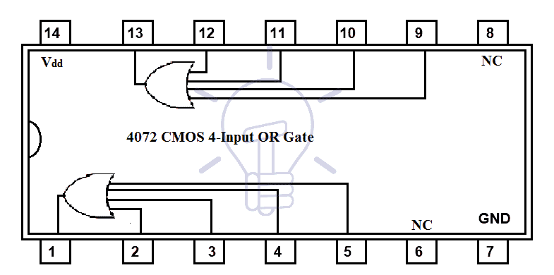
Commercially up to 4-Input OR gate IC’s are available in the market, having two OR gates in a single package.

Such as:

TTL Logic OR Gates

  • 74LS32 Quad 2-input OR Gate
  • 744075 TTL 3-Input OR Gate

CMOS Logic OR Gate

  • CD4071 Quad 2-input OR Gate
  • CD4075 Triple 3-input CMOS OR Gate
  • CD4072 Dual 4-input CMOS OR Gate

Hex 2-input OR drivers

  • 74832

4071 CMOS and 7432 TTL OR Gate IC (2-Input)

Pinout for 7432 TTL OR Gate IC
PIN Number Description
1 Input Gate 1
2 Input Gate 1
3 Output  Gate 1
4 Input Gate 2
5 Input Gate 2
6 Output Gate 2
7 Ground
8 Output Gate 3
9 Input Gate 3
10 Input Gate 3
11 Output Gate 4
12 Input Gate 4
13 Input Gate 4
14 Positive Supply

4075 CMOS and 744075 TTL OR Gate IC (3-Input)

4072 CMOS OR Gate IC (4-Inout)

Commonly available OR Logic Gate IC are given in the table below:

4071 Quad 2-Input OR Gate
4072 Dual 4-Input OR Gate
4073 Triple 3-Input AND Gate
4075 Triple 3-Input OR Gate
7432 Quad 2-Input OR Gate
741G32 Single 2-Input OR Gate
741G86 Single 2-Inout Exclusive OR Gate
74832 Hex 2-Input OR Drivers
741G3208 Single 3-Input OR-AND Gate
744075 Single 3-Inpout OR Gate
744078 8-input OR / NOR Gate

OR Gate Applications

OR Gate has been widely used in practical life applications such as:

  • To detect exceed of specific quantities / parameters (such as temperature or pressure) and produce command signal for the system to take required action.
  • Alarm circuit for car door system
  • In calculators, computers and digital logic circuits.

The post Digital Logic OR Gate appeared first on Electrical Technology.


April 07, 2018 at 04:38AM by Department of EEE, ADBU: https://ift.tt/2AyIRVT

The Essentials Of Substations, Electrical Equipment and Busbar Arrangements

Electrical power systems nowadays are generated, transmitted, and distributed in the form of alternating current. The electric power is produced at the power stations which are located in suitable places,... Read more

The post The Essentials Of Substations, Electrical Equipment and Busbar Arrangements appeared first on EEP - Electrical Engineering Portal.


Credit- Electrical Engineering Portal. Published by Department of EEE, ADBU: tinyurl.com/eee-adbu