Thumb Rules-13 ( Quick Reference Earthing -CPWD)


Earthing Strip for Sub-Station Equipment

CPWD-TABLE VIII

Type of Installation Earth Electrode Earth Strip
Indoor sub-station with HT panel, Transformer capacity up to  1600  KVA, LT panel, D.G Set. Copper Plate 25 x 5 mm Copper Strip
Indoor sub-station with HT  panel, Transformer  capacity  above  1600  KVA, LT panel, D.G Set Copper Plate 32 x 5 mm Copper Strip
HT Outdoor sub-station Copper Plate 25 x 5 mm Copper Strip
LT Indoor sub-station with generator Copper Plate 25 x 5 mm Copper Strip
LT   switch   room   with Main   LT  D.B Copper Plate 20 x 3 mm Copper Strip


Neutral Earthing of Transformers and Generators

CPWD-TABLE VIII

Type of Installation Earth Electrode Earth Strip for Neutral
Transformer  of  capacity  up  to  1600 KVA Copper Plate 25 x 5 mm Copper strip
Transformer  of  capacity  above  1600  KVA Copper Plate 32 x 5 mm Copper strip
Generating set of all capacity Copper Plate 26 x 5 mm Copper strip
Type of Installation Earth Electrode Earth Strip for Neutral
Transformer  of  capacity  up  to  1600 KVA Copper Plate 25 x 5 mm Copper strip


Earthing Strip for Bus Trunking and Rising Main

CPWD-TABLE VIII

Type of Installation Material of Main Conductor Earth Strip
Bus   trunking   up   to   2500   Amp   capacity Copper/ Aluminum 2 No 25 x 5 mm Copper Strip
Bus   trunking   above   2500   Amp   capacity Copper/ Aluminum 2 No 32 x 5 mm Copper Strip
Bus  trunking for  generating set and LT panel Copper/ Aluminum 2 No 25 x 5 mm Copper Strip
Rising main up to 400 Amp capacity Copper/ Aluminum 2 No 20 x 5 mm Copper Strip
Rising  main  above  400  Amp  and  up to 800 Amp Copper/ Aluminum 2 No  20 x 3 mm Copper Strip


The Size of Earthing conductors

As per CPWD

Size of phase conductor Size of Earthing conductor of the same material as phase conductor
Up to 4 sq.mm. Same size as that of phase conductor
Above 4 sq.mm. up to 16 sq.mm. Same size as that of phase conductor
Above 16 sq.mm. up to 35 sq.mm. 16 sq.mm.
Above 35 sq.mm. Half of the phase conductor


Materials and Sizes of Earth Electrodes

CPWD-TABLE IX

Type of Electrodes Material Size
Pipe GI medium class 40 mm dia 4.50 m long (without any joint)
Plate (i) GI 60 cm x 60 cm x 6 mm thick
(ii) Copper 60 cm x 60 cm x 3 mm thick
Strip (i) GI 100 sq. mm section
(ii) Copper 40 sq. mm section
Conductor (i) Copper 4 mm dia (8 SWG)
Note :  Galvanization of GI items shall conform to Class IV of IS 4736 : 1986.


Minimum Sizes of Earthing Conductors for Use Above Ground

CPWD- TABLE X

Material and Shape Minimum Size
Round copper wire or copper clad steel wire 6 mm diameter
Stranded copper wire 50 sq. mm or (7/3.00 mm dia)
Copper strip 20 mm x 3 mm
Galvanized iron strip 20 mm x 3 mm
Round Aluminum wire 8 mm diameter
Aluminum strip 25 mm x 3 mm


Minimum Sizes of Earthing Conductors for Use Below Ground

CPWD- TABLE XI

Material and Shape Minimum Size
Round copper wire or copper clad steel wire 8 mm diameter
Copper strip 32 mm x 6 mm
Round galvanized iron wire 10 mm x 6 mm
Galvanized iron strip 32 mm x 6 mm


Selection of Type of Earthing Electrodes

As per CPWD

Type of electrode Application
GI pipe Internal electrical installations like Distribution Board and Meter Boards (in residential quarters), feeder pillars and poles etc.
GI plate (i) For Fire Fighting pumps and water supply pumps.
(ii) Lightning conductors.
Copper plate Neutral earthing of transformers/ generating sets.
Strip/ Conductor Locations where it is not possible to use other types.


Number of Earth Electrodes

As per CPWD

Equipment No of Earthing
For neutral earthing of each transformer 2 sets
For body earthing of all the transformers, 2 sets
HT/LT Panels and other electrical equipment
in the Sub-station/ power house
For neutral earthing of each generating set 2 sets
For body earthing of all the generating sets, 2 sets
LT panels, other electrical equipment in the generator room


Size of protective conductor

As per CPWD

Size of phase conductor Size of protective conductor of the same material as phase conductor
Up to 16 sq.mm. Same as Phase Conductor  Size
16 to 35 sq.mm. 16 sq.mm.
35 sq.mm Half Size of Phase Conductor


Earthing Points

As per CPWD

Earthing Description
Location for Earth Electrodes Normally  an  earth  electrode  shall  not  be  located  closer  than  1.5  m  from  any  building.
Installation of Pipe Pipe electrode shall be buried in the ground vertically with its top at not less than 20 cm below the ground level
Installation of Plate Plate electrode shall be buried in ground with its faces vertical, and its top not less than 3.0 m below the ground level.
The strip or conductor The strip or conductor electrode shall be buried in trench not less than 0.5 m  deep
More Earthing Electrode When more than one electrode (plate/pipe) is to be installed, a separation of not less than 2 m shall be maintained between two adjacent electrodes.
Earthing Electrode  If the electrode cannot be laid in a straight length, it may be laid in a zigzag manner with a deviation upto 45 degrees from the axis of the strip. It can also be laid in the form of an arc with curvature more than 1 m or a polygon
Earthing Pit Cover A cast iron / MS frame with MS cover, 6 mm thick, and having locking arrangement shall be suitably embedded in the masonry enclosure.
Earthing Wire Protection  The  earthing  conductor  from  the  electrode  up  to  the  building  shall  be  protected  from mechanical injury by a medium class, 15 mm dia. GI pipe in the case of wire, and by 40 mm dia, medium class GI pipe in the case of strip. The protection pipe in ground shall be buried at least 30 cm deep (to be increased to 60 cm in case of road crossing and pavements)
No of Earthing Conductor Two protective conductors shall be provided for a switchboard carrying a 3-phase switch gear there on.
Earthing Electrode  No earth electrode shall have a greater ohmic resistance than 5 ohms as measured by an approved earth testing apparatus. In rocky soil the resistance may be up to 8 ohms.
Earthing Resistance Each   of   the   earth   stations   should   have   a   resistance   not   exceeding   the product  given  by  10  ohms  multiplied  by  the number  of  earth  electrodes  to be  provided  therein.  The  whole  of  the  lightning  protective  system,  including any  ring  earth, should  have  a  combined  resistance  to  earth  not  exceeding 
10 ohms without taking account of any bonding
More Earthing Resistance If the value obtained for the whole of the lightning protection system exceeds 10 ohms, a reduction can be achieved by extending or adding to the electrodes, or by  interconnecting  the  individual  earth  terminations  of  the  down  conductors  by  a  conductor


March 02, 2018 at 10:24AM by Department of EEE, ADBU: http://ift.tt/2AyIRVT

Emergency Generator Set – Construction, Installation, Maintenance & Wiring

An Overview of Emergency Generator Set

(Manuel Bolotinha)

Introduction to Emergency Generator Set

Hospitals, airports, shopping malls and office buildings, just to mention some examples, are very sensitive, in what concerns safety of people and goods, to power outages caused by faults in medium (MV) and low voltage (LV) distribution networks and even in high voltage (HV[1]) transmission networks.

When a power outage occurs is necessary that communication systems, emergency lighting, smoke exhaust fans, fire fighting water pumping stations, security, lighting in buildings and other critical electrical systems and equipments, designated as essential loads (or critical), continue running.

To solve such problems common solution is the installation of LV diesel emergency generator sets, whose applications, characteristics and installation procedures must be in accordance with IEC[2] Standard 60034.

Rated Power and Neutral Grounding of Emergency Generator

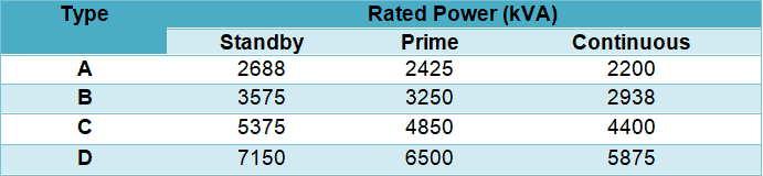
Rated power of LV diesel emergency generator sets[3] depends on the operation regime: standby, prime and continuous, as defined in ISO[4] Standard 8528.

In standby regime the available power supplied by the generator set varies with the value of the load during the lack of normal power supply and average power output is 70% of emergency standby power rating. Typical operation of this regime is 200 hours per year with a maximum of 500 hours per year.

In prime regime the available power supplied by the generator set varies with the value of the load for an unlimited period of time and average power output is 70% of prime power rating. Typical peak demand of 100% of prime-rated ekW[5] with 10% of overload capability for emergency use for a maximum of 1 hour each 12 hours; overload functioning may not exceed 25 hours per year.

In continuous regime output is available without varying load for an unlimited time. Average power output is 70 – 100% of the continuous power rating. Typical peak demand is 100% of continuous rated ekW for 100% of operating hours.

According to the definitions stated above is easy to understand that the same generator set has different rated powers for each operation regime. Rated power in standby regime is higher than rated power in prime regime, which is higher than rated power in continuous regime.

Rated power of generator sets main be defined in kVA or kW for a cos Φ (Power Factor)[6] = 0.8. It is also necessary to define the network frequency (50 Hz or 60 Hz).

In Table 1, as an example, are shown the values of rated power (kVA) of some generator sets of the same manufacturer and the same manufacturing series, according to the operation regime (f = 50 Hz).

Examples of emergency generator sets rated power according to operation regime

Table 1 – Examples of emergency generator sets rated power according to operation regime

As the LV network that the generator set wills electrically supplies is isolated and has unbalanced loads, neutral point of the windings of the alternator[7] is directly earthed since this neutral grounding system improves the behavior of the alternator with those types of loads.

Construction and Components of Emergency Generator

General Considerations

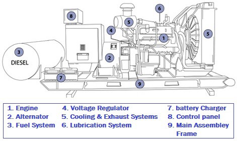
Main components of a generator set are (see Figure 1):

  • Engine
  • Alternator
  • Main assembly/Frame.
  • Starting battery and charger.
  • Lubrication system.
  • Cooling and exhaust systems, including the radiator.
  • Fuel system.
  • Voltage regulator
  • Exhaust piping and silencer.
  • Control and monitoring panel.

Construction and Components of Emergency Generator

Figure 1 – Main components of a generator set

Engine

The engine that must be in accordance to ISO Standard 3046 is an internal combustion machine, four stroke cycle and usually diesel fueled (there also models gas fueled). The power of the engine must be suitable for the rated power of the alternator.

Main components of the engine are:

  • Electronic speed governor, usually with a variation of ± 0.25
  • Acceleration control and run and stop lever
  • Standard steel ring to assure a rigid connection to the coupling system of the alternator enclosure
  • Flywheel and elastic union for alternator coupling

The engine must start and work at least 8 hours at full load, followed by 1 hour of 10% overload under the specified temperature conditions. The engine must have electrical start-up, which time shall not be higher than 10 s.

Engine cooling may be done by circulation of air or water, in a close circuit with a radiator. To improve engine start-up it must be envisaged an oil, water or combustion air pre-heating system (usually resistors), which must work with the temperature increase of carter grease.

Alternator

The alternator is of synchronous type, single or three-phase, self excited, regulated and ventilated; the ventilation of the alternator shall be performed by a shaft coaxial turbine.

Main characteristics of alternators are:

  • Rated voltage: 230 V (single-phase alternators); 400/230 V (three-phase alternators).
  • Rated frequency: 50 Hz or 60 Hz.
  • Rated power (depending on the operation regime – see Section 2).
  • Power factor: usually 0.8.
  • Insulating class: usually H.

Insulating class of alternators are established, according to IEC Standard 60085, taking into account the maximum temperature windings can withstand, since temperature is often main factor that contributes for insulating material ageing. In Table 2 are shown the alternators insulating classes.

Table 2 – Insulating of alternators

Table 2 – Insulating of alternators

Other characteristics of alternators that must be considered are:

  • Radio interferences suppression.
  • Harmonic distortion: ≤ 2 % off-load; ≤ 3.5 % with balanced load.
  • Voltage regulation: ±1.5% for off-load and full-load variations, power factor between 8 and 1 and speed variations of ± 4.5 %.
  • Capability to recover voltage up to 3% of rated voltage within 3 s, when full-load is suddenly applied with cos Φ = 0.8.
  • Capability to withstand short-circuits currents up to 300% of rated current during 5 s before the actuation of internal protection devices.

Other Components and Systems

The assembly frame of the engine and alternator (and even of the daily diesel tank) is usually constructed with standard steel profiles, electrically welded, and anti-vibrate supports shall be installed; these profiles must be calculated in order that the self vertical oscillation should be around 7 Hz.

The starting battery is lead-acid type and connected to a battery charger that will assure the maintenance charge of the battery and is normally installed in the control and monitoring panel.

Exhaust piping must include a silencer (see Figure 2) and a flexible connection from exhaust outlet of the engine to the outgoing pipe. Both silencer and piping must be thermally insulated with glass wool covered with aluminum sheet.

Exhaust piping of a generator set

Figure 2 – Exhaust piping of a generator set

Fuel system includes the daily tank (with level indicator and maximum and minimum level switches) and must have such a capacity that assures the generator set woks during a defined time period, at full-load rated power for the established operation regime.

This system may also include an eventual diesel cistern, transfer pumps of daily tank (manual and electrical) and the required piping.

Control and Monitoring Panel

In the control and monitoring panel it shall be Installed the following equipment:

  • Metering equipment (ammeters; voltmeters; frequency meter).
  • Control and monitoring equipment: start and stop push-buttons; oil manifold; water thermometer.
  • Control switch with 4 positions: Automatic/Manual/Test/Out-of-service.
  • Start and stop generator set automatic system.
  • Circuit breaker for alternator protection.
  • Monitoring lamps.
  • Emergency shutdown system of the engine.
  • Battery charger (see Section 3.4).
  • Control and monitoring equipments for all the auxiliary components of the generator set.

Installation Procedures of Emergency Generator Set

Generator sets are usually installed indoors, in a dedicated room, which must be provided with incoming and outlet grilles, calculated to assure the required air flow for equipment cooling.

Outgoing air grille is installed face to the radiator and shall allow an easy dismantling for generator set removing. In situations where is not possible to assure the required air flow for generators set cooling it is necessary to install radiator separated from the engine.

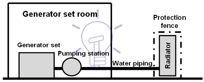
In these situations generator set cooling is done through fresh water circulation in a close circuit, using a centrifugal pump. Temperature is thermostatically controlled and heat dissipation is achieved by radiator, installed at the primary circuit, and a fan. The radiator must have a low noise level and must be mounted on anti-vibrate supports.

Figure 3 gives an example of what was explained above.

Figure 3 – Installation scheme of a Generator set with separated radiator

If the noise level of the generator set is too high according to noise regulations, namely in circumstances where the equipment is installed outdoors, the generator set must be installed inside an enclosure, as shown in Figure 4.1500kVA Cummins closed generator

Figure 4 – Generator set inside an enclosure

Maintenance of Emergency Generator Set

As referred in Section 1 generators sets play a critical role in safety of people and goods of certain electrical installations and for that reason is important to establish an accurate maintenance program that must include:

  • Run monthly, or twice a month, at off-load conditions for a period of 4 hours (to assure that it will run when necessary).
  • Manual running.
  • Generator set start in case of absence of network voltage and verification of the functioning of the automatic inverter switch.
  • Visual inspection.
  • Verification of earthing connection of neutral and all metallic parts.
  • Verification of oil level and
  • Battery status (visual inspection; voltage measurement of the elements; situation of the electrolyte).

Generator Start-Up. Automatic Transfer System

Generator set start-up shall me automatic, when there is an undervoltage or a negative sequence voltage in the power supply network and it is done through an automatism system installed in the generator set control and monitoring panel. This automatism system will provide also the disconnection and the stop of the generator set when the network voltage returns to normal.

The above referred automatism system will control the automatic transfer system, hereafter referred as automatic inverter switch, and must assure a number of start-up consecutive trials (never less than 3) with a time between trials that is the required time for battery regeneration.

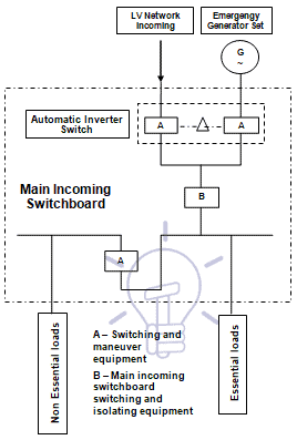
Automatic inverter switch, which preferably shall be installed in the main incoming switchboard, must provide transfer of essential loads to the generator set power supply when a disturbance in the network voltage occurs and provide the re-transfer of those loads to network power supply when the situation backs to normal.

The automatic inverter switch may be built with 2 of the following equipments:

Those equipments must have a mechanical and electrical interlocking to avoid the parallel association between the network and the generator set.

All switchboards must have disconnecting equipment (circuit breaker; on-load switch; contactor) to split the loads between essential and non essential, to avoid these loads to be powered by the generator set.

Figure 5 shows an example of a schematic diagram of a transfer system.Schematic diagram of transfer system

Figure 5 – Schematic diagram of transfer system

Wiring & Connection of Portable Generator

You can wire and connect a portable generator to the home supply system by three methods here.

[1] HV: Us ≥ 60 kV; MV: 1 kV < Us ≤ 49.5 kV; LV: Us ≤ 1 kV. Us is the rated voltage of the network.

[2] IEC: International Electrotechnical Comission.

[3] Hereafter we will use the expression generator sets to refer to LV diesel emergency generator sets.

[4] ISO: International Organization for Standardization.

[5] ekW: Electrical active power.

[6] cos Φ: power factor.

[7] See Section 3.3.

About the Author: Manuel Bolotinha

-Licentiate Degree in Electrical Engineering – Energy and Power Systems (1974 – Instituto Superior Técnico/University of Lisbon)
– Master Degree in Electrical and Computers Engineering (2017 – Faculdade de Ciências e Tecnologia/Nova University of Lisbon)
– Senior Consultant in Substations and Power Systems; Professional Instructor

The post Emergency Generator Set – Construction, Installation, Maintenance & Wiring appeared first on Electrical Technology.


March 01, 2018 at 06:52AM by Department of EEE, ADBU: http://ift.tt/2AyIRVT
Transformers Fire Protection System – Causes, Types & Requirements

Basic Requirements for Transformers Fire Protection System

By: Manuel Bolotinha

Causes of Fire in Transformers

Excessive overheating, extremely severe short circuits, faults in the oil and lightning strokes may cause a fire on transformers.

Transformer fires are rare but the impact is great. Even though a transformer involved in a fire likely will be destroyed almost immediately, as seen in the figure below, the fire’s effect on adjacent equipment and structures can be mitigated and therefore must be considered.

Transformers Fire Protection System – Causes, Types & Requirements

An uncontained fire can do a significant amount of damage and result in a prolonged and unscheduled outage.

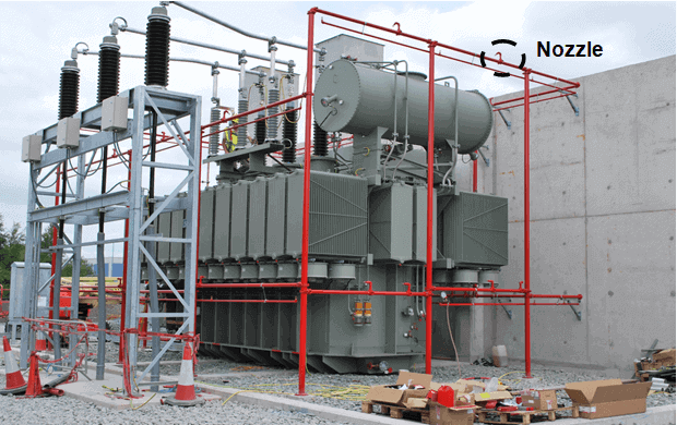
For transformers of high rated power and voltages above 123 kV is usual to provide a fire protection system, using water spray fixed systems, commonly called transformer “deluge” or “fire water” systems, as shown in Figure 1Transformers Fire Protection system

Figure 1 – Transformer fire protection system

This system is activated through flame detectors if the transformer is installed outdoors, or by smoke detectors, if the transformer is installed indoors.

Types of Fire Protection System of a Transformer

Fire protection system of a transformer may be divided into:

  • Water Based and Mist Systems: fire pumps; water spray fixed system/nozzles; valves; valves components; piping.
  • Fire Detection System: fire detectors; control panel; cabling.

Also read: TRANSFORMER NAMEPLATE (GENERAL REQUIREMENTS).

Fire suppression requirement may be mitigated when the transformer is located remotely from the structure and other equipment, or the burning oil can be contained.

Protection of the plant structure and adjacent equipment, as well as reducing hazards to personnel, warrants fire suppression in most cases.

In some cases, use of less-flammable insulating fluids may mitigate the need for fire suppression and should be considered as an alternative.

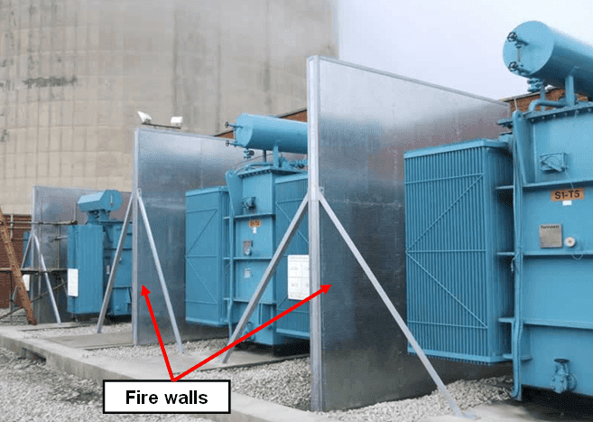
In common practice that industry standards and insurance requirements include fire suppression and fire walls (Figure 2) for transformers containing as little as about 1,900 l of combustible oil where acceptable separation/barriers from buildings and other equipment cannot be achieved.

Transformers Fire Protection System - Causes, Types & Requirements

Figure 2 – Fire walls

Requirements for Transformer Fire Protection

Summarizing, the basic principles are:

  • New facilities with large, mineral-oil-filled transformers located near the plant structure or other equipment should include active transformer fire suppression systems to protect the structure and adjacent equipment and properly designed containment systems to protect the environment.
  • For new facilities, and where justified at existing plants, serious consideration should be given to locating mineral-oil-filled transformers away from the plant, other equipment, and waterways as a way of reducing fire and environmental risks. In these cases, active fire suppression may not be necessary if other considerations allow.
  • Existing, functional fire suppression systems should continue to be used to protect plant structure and other equipment but should be reviewed for adequacy and compliance with current codes and standards.
  • Inactive fire suppression systems should be reviewed for adequacy and compliance with current codes and standards and restored to service.
  • Fire suppression systems should be added to existing facilities (where none currently exist) and where required to protect the plant structure or other equipment.
  • Transformers should have periodic condition assessments in addition to routine inspection, testing, and maintenance. Transformers with low condition indices should be programmed for rehabilitation or replacement.
  • Fire walls between adjacent transformers, between transformers and the plant structure, between single-phase transformers, or between transformers and other equipment should be added where feasible and appropriate to contain a fire and explosion, thus reducing collateral damage.
  • Fire suppression systems must be adequately operated, maintained, and tested.
  • Containment and oil-water separation structures must comply with all applicable laws, regulations, and standards.
  • Access to transformers will be limited only to those having official business in the area. Proximity of the public to transformers will be restricted.
  • Applicable environmental laws must be accommodated.

Also read: Transformers MCQs With Explanatory Answers

Download Project Report on Transformer Fire Protection

  • Title:
  • Format:
  • Size:
  • Pages:
  • Download:
GUIDE FOR TRANSFORMER FIRE SAFETY PRACTICES
PDF
4MB
139

About the Author: Manuel Bolotinha

-Licentiate Degree in Electrical Engineering – Energy and Power Systems (1974 – Instituto Superior Técnico/University of Lisbon)
– Master Degree in Electrical and Computers Engineering (2017 – Faculdade de Ciências e Tecnologia/Nova University of Lisbon)
– Senior Consultant in Substations and Power Systems; Professional Instructor

You may also read:

The post Transformers Fire Protection System – Causes, Types & Requirements appeared first on Electrical Technology.


February 28, 2018 at 06:22AM by Department of EEE, ADBU: http://ift.tt/2AyIRVT
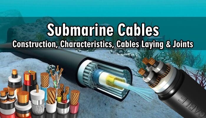
Submarine Cables – Construction, Characteristics, Cables Laying & Joints

An Introduction to Submarine Cables & Subsea Power Cables

Introduction to Submarine Cables

The development of offshore wind farms and oil and gas offshore platforms requires the installation of power, control and monitoring and communications cables between the platforms and the main land.

For this purpose submarine cables are installed, which are also used for power and/or communications between islands and the main land, between countries and even between continents.

Submarine Cables – Construction, Characteristics, Cables Laying & Joints

Characteristic of Submarine Cables

Submarine cables, that must comply with IEC Standard 60288[1], are specifically designed and manufactured to be installed underwater, laid at seabed, taking into account that seabed is rugged and rocky, that there are marine animals, which can damage the cables, and that is mandatory that cables must withstand tsunamis and volcanic activity, as well as trawls used by fishermen, that are more hazardous than the fish itself.

To establish the characteristics of a submarine cable is necessary to consider the following parameters:

  • Ambient temperature (seabed and land).
  • Burial depth.
  • Particular burial/protection requirement at shore approach (deeper burial, directional drill pipe…).
  • Axial spacing of cables.
  • Thermal resistivity of seabed and land.
  • Length of submarine cable.
  • Water depths.

Typical rated voltages of power submarine cables are 3.6/6(7.2) kV to 290/500(525) kV, in AC systems, and higher in DC systems.

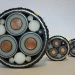
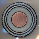
Depending of rated voltage and of the cross section (for DC systems manufacturers construct these cables with cross sections up to 2500 mm2 and for network rated voltage up to 725 kV) they may be multicore or single core.

Characteristics of Power Submarine Cables

Main characteristics of power submarine cables are:

  • Conductor: Copper or aluminum. In case that the conductors are going to be used in long depths and if requested the conductor is sealed with special material which prevents the water penetration in case of cable damage.
  • Insulation: XLPE, EPR or MIND (mass impregnated paper).
  • Screening: Copper wires or tapes and lead sheath where required.
  • Armoring: The protection of the cable from mechanical stresses is achieved by the armoring consisted of steel wires (for single core cables armoring must be of non-magnetic material – usually aluminum – to avoid overheating of armoring due to Foucault currents[2]Joule effect), which provide also to the cables the required mechanical strength which during laying or pulling. The steel wires are of different categories of breaking load and they are heavily galvanized.
  • Outer protection: The outer protection of the cable, according to the conditions and requirements of the installation, is achieved by PVC or PE sheath and layers of polypropylene yarns or jute.

Also read: Types Of Cables Used In Internal Wiring

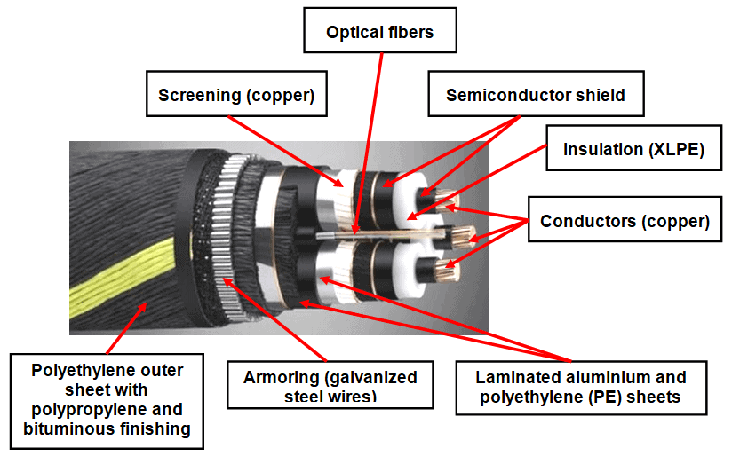
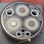
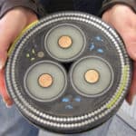
Three-core power cables may also have optic fiber cables for communications, as shown in Figure 1

Figure 1 – Construction of Three-phase submarine cable

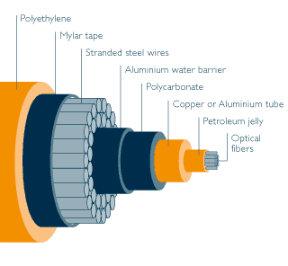
When single core power cables are used usually they do not include the optical fibers and in this situation is necessary to install also optical fiber submarine cables like the one shown in Figure 3.Optical fiber submarine cable

Figure 2 – Optical fiber submarine cable

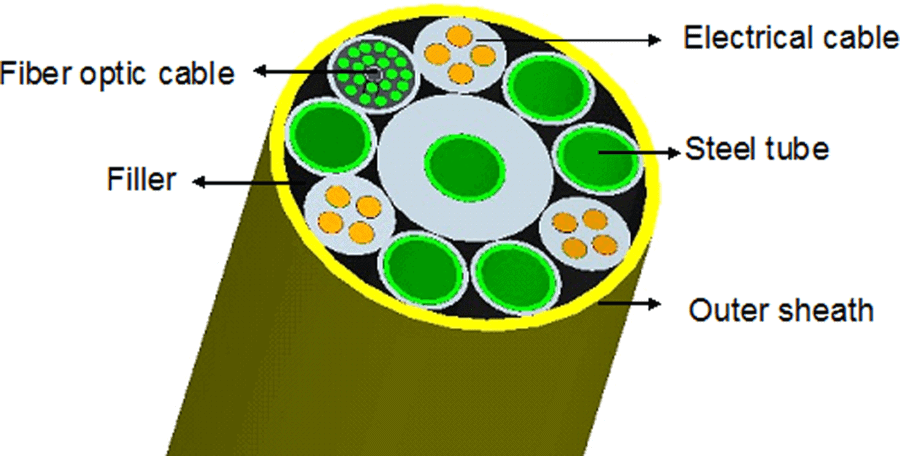
Some manufacturers include in the same submarine cable communications (optical fiber) and controls to subsea processing and boosting systems, whether requirements are for low voltage, medium voltage or high voltage power supply – umbilical cables (see Figure 3).

Umbilical cables may also include low and high pressure lines (steel tube) used for fluids.Umbilical cable

Figure 3 – Umbilical cable

Basic Procedure for Submarine Cables laying

Laying a submarine cable is a remarkably complex, hazardous and expensive business.

Routes need to be surveyed, technology developed, the cable needs to be laid without being lost, broken or damaged.

Prior to install a submarine cable is necessary to undertake a series of actions:

  • Choose the routing, using updated nautical maps.
  • Evaluate the geological conditions of the chosen routing.
  • Proceed to seabed identification, namely in what concerns bathymetry (depth), slope, existence of topographic incidents, lithology (seabed nature), environment conditions, such as saltiness, temperature and pH, and the dynamic movements that may exist at seabed (waves, sea currents, etc.) or that may affect it (tsunamis, volcanic activity, sludge currents, etc.).

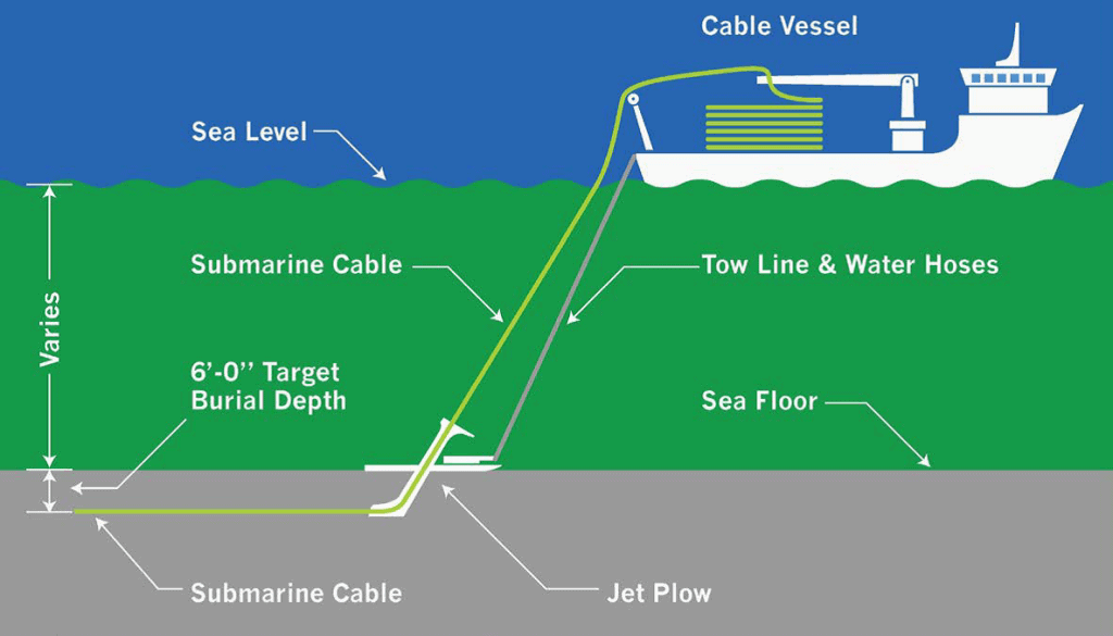
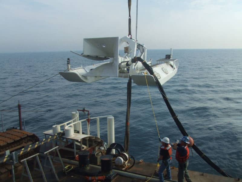
Once the routing is chosen and all studies of seabed are completed, it is necessary to find if there any stretches were the cable needs to be buried (using a hydro jet burial machine) and to develop specific technologies to constantly survey the place where the cable is installed to avoid damages or cable loose.

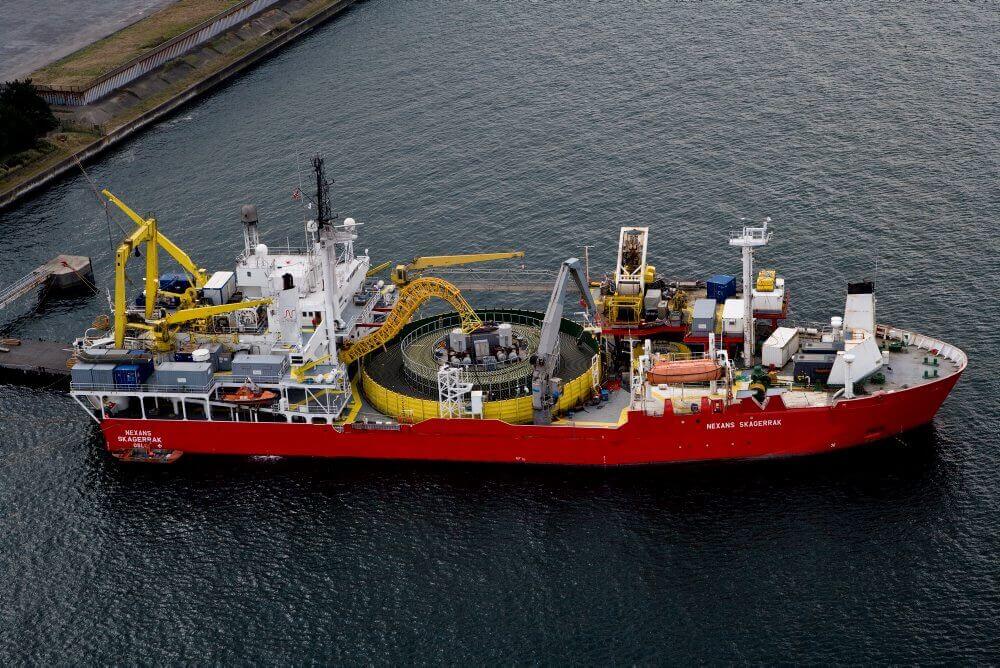
Submarine cables is generally done by a cable laying ship, as seen in Figures 4 and 5, and robots may be used to control cable laying (see Figure 6).

Cable laying ship

Figure 4 – Cable laying ship

Submarine cable laying

Figure 5 – Submarine cable laying

Cable laying robot

Figure 6 – Cable laying robot

Submarine Cable Joints

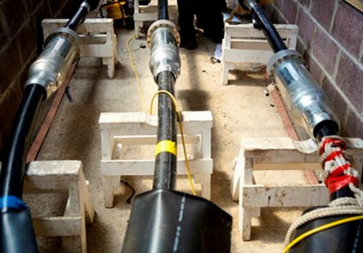
When submarine cable run is very long or if damage occurs in the cable it is necessary to install cable joints.

These cable joints, that are subjected to high pressures, are executed prior the cable installation in seabed (whenever possible at the manufacturer facilities), must be submitted to insulation and dielectric tests and also to ultrasonic and radiographic tests, in order to assure the reliability of the installation.

Figure 7 shows a phase of submarine cable joints.

Execution of submarine cable joint

Figure 7 – Execution of submarine cable joint

Good to know:

[1] IEC: International Electrotechnical Comission.

[2] Foucault currents are induced currents (magnetic induction phenomenon).

Gallery of Submarine / Subsea & Power Submarine Cables

About the Author: Manuel Bolotinha

-Licentiate Degree in Electrical Engineering – Energy and Power Systems (1974 – Instituto Superior Técnico/University of Lisbon)
– Master Degree in Electrical and Computers Engineering (2017 – Faculdade de Ciências e Tecnologia/Nova University of Lisbon)
– Senior Consultant in Substations and Power Systems; Professional Instructor

You may also read:

The post Submarine Cables – Construction, Characteristics, Cables Laying & Joints appeared first on Electrical Technology.


February 27, 2018 at 06:12AM by Department of EEE, ADBU: http://ift.tt/2AyIRVT

Design of Grounding / Earthing System in a Substation Grid

Design of Earthing / Grounding System in a Substation Grid

By: Manuel Bolotinha

Introduction to Substation Earthing Grid

In high and medium voltage[1]Air Insulated Substations (AIS) the electromagnetic field, which causes are the static charges of bare cable and conductors and by the atmospheric conditions (surges), induce voltages at no-live parts of the installation that create potential differences between metallic parts and ground and also between different points of the ground.

Similar situations can occur when there are faults between live parts of the installation and no-live parts, for example in phase-to-earth short circuit.

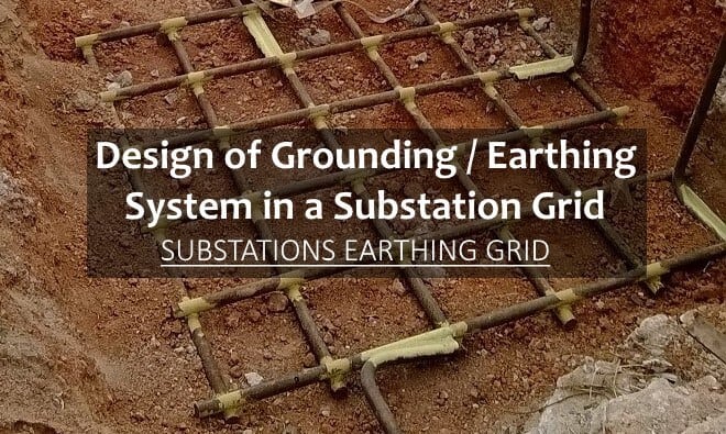
Design of Grounding Earthing System in a Substation Grid - Substation earthing grid

These potential differences give origin to step potential and touch potential, or a combination of both, that can lead to circulation of an electric current through the human body, that can cause hazardous to people.

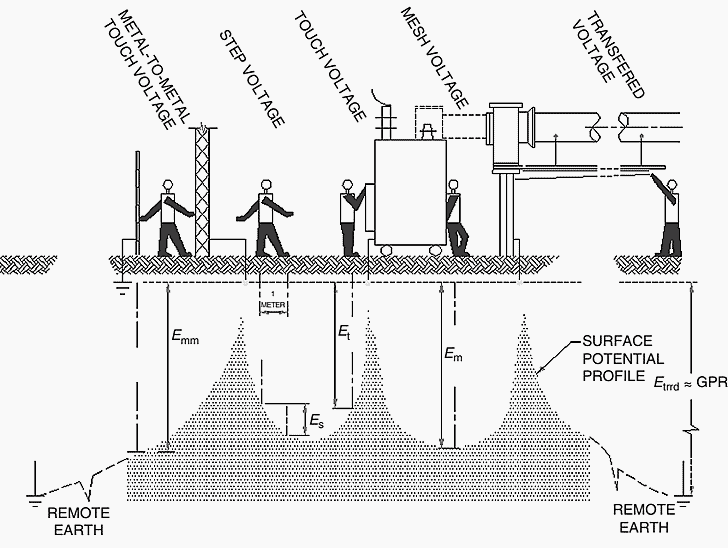
Touch voltage (Et) can be defined as the maximum potential difference that exists between an earthed metallic structure capable to be touched by the hand and any point of the ground, when a fault current flows.

It is usual to consider a distance of 1 m between the metallic structure and the point on the ground.

Step voltage (Es) is defined as the maximum potential difference that exists between the feet when a fault current flows.

It is usual to consider a distance of 1 m between the feet.

A particular case of step voltage is the Transferred voltage (Etrrd): where a voltage is transferred into or out of the substation from or to a remote point external to the substation site.

Other concepts are:

  • Ground potential rise (GPR): The maximum electrical potential that a substation grounding grid may attain relative to a distant grounding point assumed to be at the potential of remote earth. This voltage, GPR, is equal to the maximum grid current times the grid resistance.
  • Mesh voltage (Em): The maximum touch voltage within a mesh of a ground grid.
  • Metal-to-metal touch voltage (Emm): The difference in potential between metallic objects or structures within the substation site that may be bridged by direct hand-to-hand or hand-to-feet contact.

The diagram in Figure 1 shows the phenomena referred above.Touch, step and transferred voltages - Design of Earthing / Grounding System in a Substation Grid

Figure 1 – Touch, step and transferred voltages

In order to minimize to acceptable values of the currents through the human body, to ensure electrical safety for people working within or near the installation, and also to limit any eventual electrical interference with third-party equipment, AIS must be provided with an earthing (or grounding) system, to which all metallic non-live parts of the installation must be connected, such as metallic structures, earthing switches, surge arresters, enclosures of switchboards and motors, transformers rails and metallic fences.

Since earthing has an influence on the levels of power system overvoltages and fault current, and the definition of protection systems, earthing system must be designed to ensure that there is proper operation of the protective devices such as protective relaying and surge arresters.

Design and construction of earthing system must assure that system performs for the expected life of the installation and it must therefore take into account future additions and the maximum fault current for the ultimate configuration.

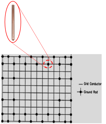
Earthing system is made of a mesh of buried bare copper cable, with additional earth rods, and shall be calculated, being recommended to use IEEE Std. 80-2000.

Important formulas for Designing a Substation Grid Earthing System

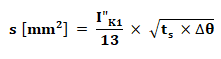
The cross section of the buried cable should calculated in accordance with the value of the phase-to-earth short circuit current, but it is common to use the three phase short-circuit current for this purpose.

For this calculation the following formula must be used:Where:

  • I”K1 is the phase-to-earth short-circuit current [A]
  • ts is the duration of the fault [s]
  • Δθ is the maximum admissible temperature rise [°C] – for bare copper Δθ = 150 °C

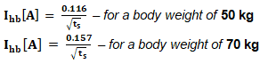
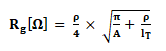
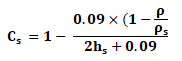
According to the referred IEEE Standard maximum tolerable step and touch potential and maximum tolerable current through the human body (Ihb) and the resistance of the earth grid (Rg) are calculated by the formulas:

Maximum tolerable step potential

Maximum tolerable touch potential

Maximum tolerable current through the human body

Resistance of the Earth GridResistance of the earth grid

Where:

  • Cs is the surface layer derating factor and is calculated by the formula:
  • ts is the duration of the fault [s]
  • ρs is the surface material resistivity [Ω.m] typical value for wet crushed rock/gravel: 2,500 Ω.m
  • ρ is the resistivity of the earth beneath the surface material [Ω.m]
  • hs is the thickness of the surface material [m]
  • A is the area occupied by the ground grid [m2]
  • lT is the total buried length of conductor, including the earth rods [m]

If no protective surface layer is used, then Cs =1 and ρs = ρ

These calculations are usually done using specific software.

Substation Earthing Grid

Figure 2 shows an example of the earth grid.Earth grid

Figure 2 – Earth grid

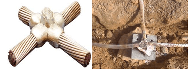
The most suitable methods for the connection of the earth grid connections are:

a.) Exothermic welding

Exothermic welding

Figure 3 – Exothermic welding

Exothermic welding is conductors’ permanent connection process that uses molten metal and molds, which is based in a chemical reaction between metal oxides (the conductor) and ignited aluminium powder, which acts as fuel, with heat energy release. This chemical reaction is a pyrotechnic composition known as thermite.

It must be assured that the number of exothermic welding done with each mold will not exceed the indications of the manufacturer.

b.) C connector:

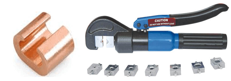
using a hydraulic crimping tool and matrixes with a size suitable for the size of the connectors.C connector and crimping tool

Figure 4 – C connector and crimping tool

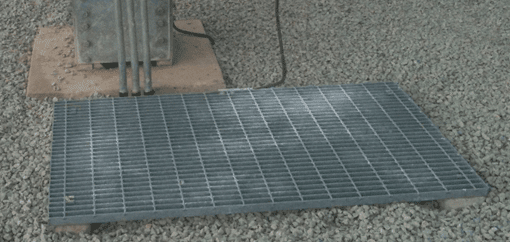
Close to the control boxes of circuit breakers, switches and isolators it must be installed a metallic equipotential mat, connected to the earth system, similar to the one shown in Figure 5.

Figure 5 – Metallic equipotential mat

Good to know:

[1] Being Un the rated voltage of the network: HVUn ≥ 60 kV; MV1 kV < Un ≤ 49.5 kV.

About the Author: Manuel Bolotinha

-Licentiate Degree in Electrical Engineering – Energy and Power Systems (1974 – Instituto Superior Técnico/University of Lisbon)
– Master Degree in Electrical and Computers Engineering (2017 – Faculdade de Ciências e Tecnologia/Nova University of Lisbon)
– Senior Consultant in Substations and Power Systems; Professional Instructor

You may also read:

The post Design of Grounding / Earthing System in a Substation Grid appeared first on Electrical Technology.


February 25, 2018 at 04:08AM by Department of EEE, ADBU: http://ift.tt/2AyIRVT