Introduction to Harmonics – Effect of Harmonics on Power System

What are Harmonics and How to Filter and Eliminate it.

(Manuel Bolotinha)

Introduction to Harmonics

The quality of electrical power supply is an important issue both for utility companies and users, but that quality may affected by electromagnetic disturbances.

Among these disturbances it must be highlighted harmonics that happens in all voltage levels and whose study, calculation of acceptable values and correction methods are defined in IEC[1] Standard 61000-2-4: Electromagnetic compatibility (EMC)[2] – Environment – Compatibility levels in industrial plants for low-frequency conducted disturbances.

Introduction to Harmonics

What are Harmonics?

Alternators produce alternated voltages (V) and currents (I) with a sinusoidal wave form and a frequency (f) of 50 Hz or 60 Hz (this frequency, the first harmonic, is usually designated by industrial frequency or fundamental), what can be observed in Figure 1.Sinusoidal alternated voltage
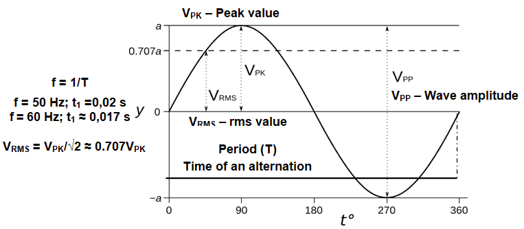
Figure 1 – Sinusoidal alternated voltage

However, due to some equipments characteristics, which are installed in the network, voltages and/or currents with different frequencies, odd integral multiples of industrial frequency, may be induced in the network, the harmonics, i. e.: 3th harmonic150 Hz or 180 Hz; 5th harmonic250 Hz or 300 Hz; 7th harmonic350 Hz or 420 Hz; etc.

We can say then that harmonics are continuous (steady-state) disturbances or distortions on the electrical network and are a completely different subject or problem from line spikes, surges, sags, impulses, etc., which are categorized as transient disturbances.

Figure 2 shows examples of 1st harmonic, 3th harmonic and 5th harmonic.Fundamental, 3th harmonic and 5th harmonic waves
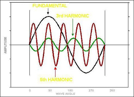
Figure 2 – Fundamental, 3th harmonic and 5th harmonic waves

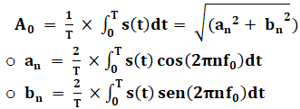
The presence of harmonics gives origin to a distorted wave of voltage (or current) that may be observed in Figure 3, taking into account that all complex waveforms can be resolved into a series of sinusoidal waves of various frequencies, therefore any complex waveform is the sum of a number of harmonics of lesser or greater value.

Fourier series[3] expresses the instantaneous value of that sumu(t) – by the equation:EquationWhere:

  • t is the time [s]
  • ω = 2πf [s-1]
  • T is the period [s]
  • f0 is the fundamental frequency [Hz]
  • s(t) is a periodic function integrable in the interval [0, T]
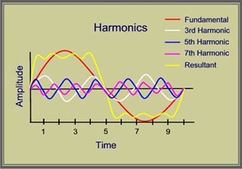
Harmonic distortion

Figure 3 – Harmonic distortion

Usually 3th harmonic is the most harmful, but in certain conditions, 5th and 7th harmonics cannot be overlooked.

Harmonic Distortion

According to IEC Standard 61000-2-4 harmonic distortion is characterized by the parameter THDTotal Harmonic Distortion – calculated by the equation:

Where Q1 represents the rms value of the voltage or of the current at industrial frequency and Qi the harmonic wave of order i (2nd harmonici=2; 3th harmonic i=3; etc.) of the voltage or of the current.

The same IEC Standard defines also the following parameters:

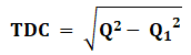
  • TDC (Total Harmonic Content), which rms value is calculated by the equation:equation

Where Q1 represents the rms value of the voltage or of the current at industrial frequency and Q the rms value of the voltage or of the current.

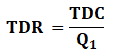
  • TDR (Total Harmonic Ratio) – relation between the rms value of TDC and the rms value of the voltage or of the current at industrial frequency (Q1), which is calculated by the equation:equation

Usually calculations are made for the voltage, considering minimum three-phase short-circuit power (S”K) of the network and maximum values (in Ω) of short-circuit impedance in the points where THD is calculated (ZK; RK; XK[4]); a specific software is required to do these calculations.

The above referred IEC Standard defines 3 classes for electromagnetic environment[5]:

  1. Class 1: This class applies to protected supplies and has compatibility levels lower than those on public networks. It relates to the use of equipment very sensitive to disturbances in the power supply, for instance electrical instrumentation in laboratories, some automation and protection equipment, some computers, etc.
  2. Class 2: This class applies generally to PCC[6] and to IPC[7] in the environments of industrial and other non-public power supplies. The compatibility levels of this class are generally identical to those of public networks. Therefore, components designed for supply from public networks may be used in this class of industrial environment.
  3. Class 3: This class applies only to IPC in industrial environments. It has higher compatibility levels than those of class 2 for some disturbance phenomena. For instance, this class should be considered when any of the following conditions are met: a major part of the load is fed through converters; welding machines are present; large motors are frequently started; loads vary rapidly.

Harmonic compatibility levels[8] (Uh [%]) for odd frequencies multiples of 3 are indicated in Table 1and for odd frequencies not multiples of 3 are indicated in Table 2.

Table 1 – Levels of harmonic compatibility for odd frequencies multiples of 3
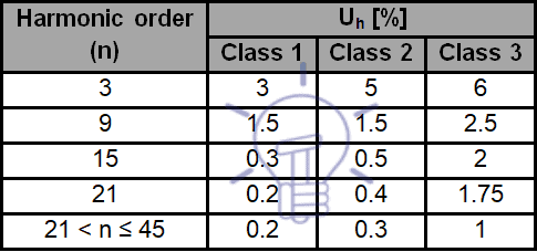
Levels of harmonic compatibility for odd frequencies multiples of 3

Table 2 – Levels of harmonic compatibility for odd frequencies multiples of 3
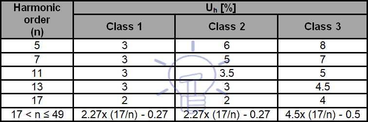
Levels of harmonic compatibility for odd frequencies multiples of 3

Compatibility levels of THD for each of the classes are:

  • Class 1 – 5%.
  • Class 2 – 8%.
  • Class 3 – 10%.

Sources and Effects of Harmonics

Harmonics are a permanent source of problems in electrical equipments and systems.

The following types of loads (non-linear loads [9]) are the main sources of harmonics:

  • Power electronic equipment (example: rectifiers – namely those used in electrical traction systems – and static converters).
  • Arcing equipment (example: arc furnaces, AC or DC, arcing welding machines).
  • Saturable devices (example: off-load current wave absorbed by a transformer with an insufficiently large power rating).

To minimize harmonics generation rectifier units are preferably six-pulse and these type of units for electrical traction systems typically generate current harmonics of 5th, 7th, 17th and 19th order, resulting from diodes unbalancing and from network impedance.

Although of a lower magnitude, under normal working conditions of equipments and of network, it must be taken into account the risk of resonance for those frequencies.

Switching operations of capacitor banks and power transformers with a permanent overload are also an important harmonics source.

Power transformers for voltages above 60 kV with star-star connection (Yy) are equally a harmonic source. To compensate those harmonics, the referred power transformers must have a tertiary winding, delta connected.

Apart from the distortion of voltage wave, harmonics are an origin of erroneous operation of control and protection systems, due to electromagnetic interferences, increase skin effect [10], cause mechanical oscillation and vibrations of electrical machines, namely power transformers and rotating machines, decrease power factor (cos Φ), conduce to premature ageing of insulation materials, leading to the lost of their dielectric characteristics, origin overheating and losses increasing, namely power transformers and cables, and decrease useful life of equipments.

Harmonics, which are the cause of voltage wave distortion, circulating in non-linear loads, like motors, when subjected to a variable magnetic flux, induce circulating currents (Foucault currents) in conducting materials, what decrease torque.

In unbalanced systems, harmonics may cause a neutral current higher than the vectorial sum of phase currents at fundamental frequency, leading to an overload in the neutral conductor.

Skin effect increases conductors’ resistance and therefore voltage drop and losses by Joule effect. This issue is particularly sensitive in overhead lines with a voltage above 150 kV and a length of 800 km and above. Common solution to solve this problem is to use DC overhead lines, in which skin effect does not exists.

Mechanical oscillation and vibrations of rotating electrical machines may origin shaft misalignment and destruction of stator, rotor and bearings.

Losses increase in power transformers, happens in iron losses, due to Foucault currents and hysteresis[11], which are proportional to the frequency and in copper losses, due to skin effect.

Harmonics Compensation & Types of Filters

When capacitor banks are used for power factor correction, a significant harmonics component flows into the capacitor bank; in these situations is necessary to temporarily switch-off the capacitor bank to allow an accurate location of harmonics sources.

In such an installation it is crucial to verify if there is any risk of harmonic resonance caused by the specific capacitor bank harmonics. This is the first step to define the correct solution for harmonic compensation.

Once confirmed the existence of harmonics and that THD value exceeds the limit defined by IEC Standard 61000-2-4 and/or established by the utility company it is mandatory proceed to harmonic compensation; the solution to be implemented depends on the installation characteristics.

The simplest solution, used in low voltage (V ≤ 1 kV) installations, is the use of copper coils (see Figure 4) that act as high frequency filter, limit the starting current of rectifiers and restrain mutual interference.Reactance for harmonic compensation
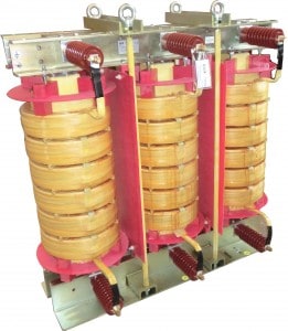
Figure 4 – Reactance for harmonic compensation

The inductance (L) of each phase is calculated by the equation:equationWhere:
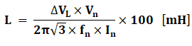
  • ΔVL is the internal voltage drop of the reactance [%]
  • Vn is phase-to-phase voltage of the network [V]
  • fn is the industrial frequency of the network [Hz]
  • In is the current [A]

In networks and installations with a strong electrical pollution (higher harmonics level), where Gh/Sn > 60% (Gh is the apparent power of all non-linear loads responsible for harmonics production and Sn is the apparent power of all upstream transformers connected to the same bus bar where loads are connected) is recommended to install harmonics filters, like the one shown in Figure 5).Harmonics filter
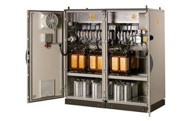
Figure 5 – Harmonics filter

Harmonics compensation may be centralized, with harmonic filters connected in the main incoming switchboard, or de-centralized or local, installing the harmonic filters close to the equipments that are the main sources of harmonics. Both solutions are shown in Figure 6.Location of harmonic filters
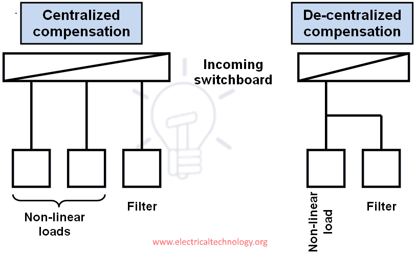
Figure 6 – Location of harmonic filters

Harmonic filters are classified into three categories:

Passive filters

These are constituted by LC series association circuits, tuned for each one of the frequencies that they are designed to compensate, usually 5th, 7th and 11th harmonics. Their main characteristics are:

  • There is no limit to harmonic to current to be eliminated.
  • They perform power factor correction.
  • They risk amplifying harmonics when there are network modifications.
  • There is an overload risk, caused by external electromagnetic pollution.

Active filters

These are constituted by electronic and micro-processed units, controlling harmonics within a range between 2nd to 50th orders; for each range of frequency it is generated a current, which has a phase shift of 180° and the same value of the harmonic current to be compensated.

This type of filters is well adapted to modifications of the network, of the loads and of the harmonic range, being particularly suitable for de-centralized or local compensation.

Hybrid filters

These are a combination of active and passive filters, controlling harmonics within a range between 2nd to 25th orders, doing also power factor correction.

Good to know:

Good to know:

[1] IEC: International Electrotechnical Comission.

[2] Electromagnetic compatibility is defined as the capability of electrical equipments to worker properly in a “electromagnetic environment” without introducing any type of electromagnetic disturbances in other equipments and systems that may exist in that environment.

[3] Fourier series are converging trigonometric series used to represent the sum of sinusoidal functions.

[4] If the values of RK e XK of the network it is usual to consider, as an approximation, RK/XK = 0.1 and the equation

ZK = √(RK2+XK2).

[5] The definition of the classes is a transcription of IEC Standard 61000-2-4.

[6] PCC: Point on a public power supply network, electrically nearest to a particular load, at which other loads are, or could be, connected.

[7] IPC: Point on a network inside a system or an installation, electrically nearest to a particular load, at which other loads are, or could be, connected.

[8] Compatibility level defines the specified electromagnetic disturbance level used as a reference level in a specified environment for coordination in the setting of emission and immunity limits.

[9] A load is said non-linear if its impedance vary with applied voltage.

[10] Skin effect is a phenomenon that can be characterized by the repulsion of electromagnetic current lines, which consequence is a tendency for AC current to flow only at the surface of conductors.

[11] Hysteresis is the by which, when magnetic field is applied to a ferromagnetic material, as the core of the transformers, the material stays permanently magnetized, even if the magnetic field is not present.

About the Author: Manuel Bolotinha

-Licentiate Degree in Electrical Engineering – Energy and Power Systems (1974 – Instituto Superior Técnico/University of Lisbon)
– Master Degree in Electrical and Computers Engineering (2017 – Faculdade de Ciências e Tecnologia/Nova University of Lisbon)
– Senior Consultant in Substations and Power Systems; Professional Instructor

The post Introduction to Harmonics – Effect of Harmonics on Power System appeared first on Electrical Technology.


February 24, 2018 at 01:45AM by Department of EEE, ADBU: http://ift.tt/2AyIRVT

Meet the Real Heart of Power System Operations – The Transmission Control Center

Transmission control center is the real heart of every utility’s power system operations. Typical transmission control centers have three main desks – the generation, transmission and scheduling desk. Let’s take... Read more

Credit- Electrical Engineering Portal. Published by Department of EEE, ADBU: tinyurl.com/eee-adbu

Short Circuit Currents And Symmetrical Components

Short Circuit Currents And Symmetrical Components

(Manuel Bolotinha)

Short Circuit Faults and Currents

Short-circuits can occur phase-to-phase and phase-to-earth, mainly due to:

  • Dielectric breakdown of insulating materials (ageing, severe overheating and overvoltages, mechanical stress and chemical corrosion are the main factors for dielectric breakdown)
  • Decrease of creepage distance (the shortest path between two conductive parts – or between a conductive part and the bounding surface of the equipment – measured along the surface of the insulation)
  • Decrease of safety distance
  • Non-controlled partial discharges (corona)

Short Circuit Currents faults And Symmetrical Components

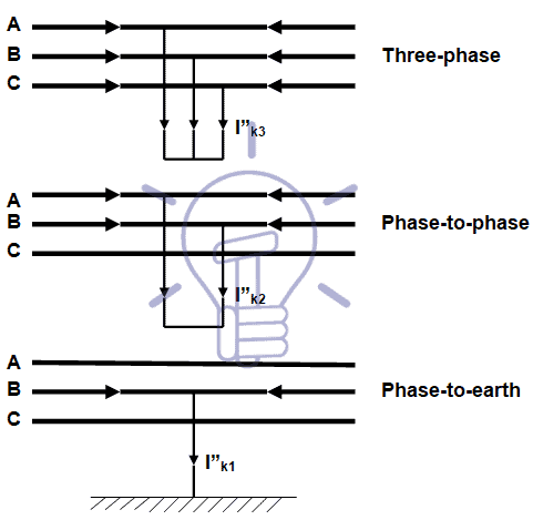
When one or more of these situations occur a “solid” or “incipient”[1] contact between conductors of different phases or between a conductor and a metallic no-live part can be established, causing a short-circuit, which diagrams are shown in Figure 1. Short-circuit diagrams

Figure 1 – Short-circuit diagrams

Phase-to-phase and phase-to-earth short-circuits may evolve towards three-phase short-circuit (the worst situation), due to dielectric breakdown caused by the high magnitude of currents.

Short-circuits cause thermal and electrodynamics stress on equipments and conductors.

Thermal stress is due to overheating of conductors (Joule law) and can cause dielectric breakdown and melting of metallic materials.

Electrodynamics stress is caused by the electromagnetic force, which is one of the four fundamental interactions in nature and it is described by electromagnetic fields that is defined by Lorentz law.

The value of this force is in direct proportion to the electric current value.

The calculation of short-circuit currents is used to design the installation and to define the characteristics of equipment, namely the breaking capacity of circuit breakers and the set-point of protection relays.

According to IEC Standard 60865-1 e 2 the equations to be used for the calculation of short-circuit currents are:

  • Phase-to-phase:
  • Three-phase

I”k3 = 1.1xUn / (√3xZd) – maximum

I”k3 = 0.95xUn / (√3xZd) – minimum

  • Phase-to-phase

I”k2 = 1.1xUn / (2xZd) – maximum

I”k2 = 0.95xUn / (2xZd) – minimum

  • Phase-to- earth:

I”k1 = 1.1xUn / (2xZd+Z0) – maximum

I”k1 = 0.95xUn / (2xZd+ Z0) – minimum

Definition of Symmetrical Components

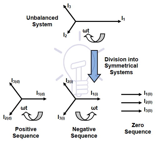
All networks and equipments have internal impedance that can be split into three symmetrical components associated with the rotation of the electromagnetic field.

An unbalance system is divided into three separated symmetrical systems:

  • Positive or synchronous sequence (Xd / Zd) – where the three fields rotate clockwise, with a phase displacement of 120°
  • Negative sequence (Xi / Zi) – where the three fields rotate anti-clockwise, with a phase displacement of 120°
  • Zero sequence (X0 / Z0) – a single fields which does not rotate, with each phase together (0° apartSymmetrical components (currents)

 Figure 2 – Symmetrical components (currents)

Once the sequence networks are known, determination of the magnitude of the fault is relatively straight forward.

The ac system is broken down into its symmetrical components as shown above.

Each symmetrical system is then individually solved and the final solution obtained by superposition of these.

Positive, negative and zero sequence impedance data are often available from manufacturers.

A common assumption is that for non rotating equipment the negative sequence values are taken to be the same as the positive (Xd = Xi / Zd = Zi)

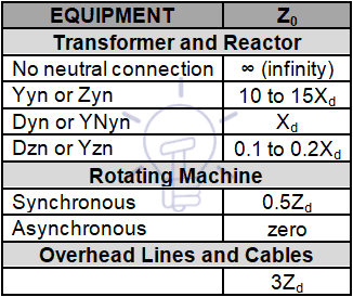
Zero sequence impedance values are closely tied to the type of earthing arrangements and do vary with equipment type.

While it is always better to use actual data, if it is not available (or at preliminary stages), the following approximations shown in Table 1 can be used.

Table 1 – Zero sequence impedance approximationZero sequence impedance approximation

Equivalent Impedance of Equipment And Network Equivalent

The equivalent impedances of equipments and upstream network are:

Generators

  • ZG = jX”d(Ω)xSn

Upstream network

  • ZN = RN + jXN
  • IZNI = 1.1xUn /√3xI”k3 or IZNI = 1.1xS”k3 /√3xUn2
  • RN = 0.1xXN (empirical)

Transformers and reactors

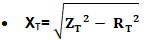
  • ZT=RT + jXT
  • IZTI = uk(%)xUn2 /100xSn
  • RT= Pcu/ 3xIn2

Motors

  • ZM = jXM
  • XM = Un/ ((Istart/In)x√3xIn
  • I”kM = 1.1xUn/√3xXM

Cables

  • ZC= ρ20°Cxl/s + j2πfxL
  • RC = ρ20°Cxl/s
  • XC = 2πfxL

Overhead Lines

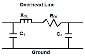
For calculation purposes an overhead line may be represented by a “π diagram”, as shown in Figure 3.Diagram of an overhead line

Figure 3 – π Diagram of an overhead line

In extra-high voltage (EHV) and high voltage (HV) overhead lines resistance of the line is usually negligible compared with the inductive reactance, but in low voltage (LV) and medium voltage (MV) overhead lines that resistance must be taken into account to calculate the impedance of the line.

For the calculation of short-circuit currents that do not involve faults to the ground th capacitive reactance is disregarded.

The equivalent positive (and negative) impedance of the line is calculated as follows:

  • ROL = ρ20°Cxl/s
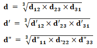
  • XOL = 2πfxl1x(μ0/2π)x(ln (d/re)+(1/4n))single-circuit line
  • XOL = 2πfxl1x(μ0/2π)x(ln (dxd’/rexd”)+(1/4n))double-circuit line

Total equivalent impedance

Legend

  • S”k3: Short circuit power
  • I”k3: Short circuit current
  • Zd: Synchronous impedance
  • Z0: Zero-sequence impedance
  • Sn: Rated power
  • Un: Rated voltage
  • In: Rated current
  • Z: Impedance
  • ӀZI: Modulus of Z
  • X: Inductance
  • X”: Sub transient reactance
  • R: Resistance
  • ρ: Resistivity
  • s: Conductor cross section
  • l: Cable length
  • l1: Overhead line length
  • d, d’, d”: Mean geometric distance between the three phase conductors of the line(s).
  • d12, d’12: distance between conductors of phases 1 and 2 (line 1 and line 2)
  • d23, d’23: distance between conductors of phases 2 and 3 (line 1 and line 2)
  • d31, d’31: distance between conductors of phases 3 and 1 (line 1 and line 2)
  • d”11, d”22, d”33: distance between conductors of phase 1 (2 and 3) of line 1 and line 2
  • re: Equivalent radius for bundle conductors
  • n: Number of strands in bundle conductor
  • μ0: Space permeability – 4πx10-4 H/km
  • ln: natural logarithm
  • L: Inductance
  • uk: Transformer impedance voltage drop
  • Pcu: Transformer resistive losses
  • f: Frequency

[1] A solid fault happens when there is a straight contact between live conductors or between live conductors and earth.

When that contact is not straight the fault is designated as incipient. Incipient faults if not cleared will evolutes towards solid faults.

About the Author: Manuel Bolotinha

-Licentiate Degree in Electrical Engineering – Energy and Power Systems (1974 – Instituto Superior Técnico/University of Lisbon)
– Master Degree in Electrical and Computers Engineering (2017 – Faculdade de Ciências e Tecnologia/Nova University of Lisbon)
– Senior Consultant in Substations and Power Systems; Professional Instructor

You may also read:

The post Short Circuit Currents And Symmetrical Components appeared first on Electrical Technology.


February 23, 2018 at 01:30AM by Department of EEE, ADBU: http://ift.tt/2AyIRVT

Counter and Types of Electronic Counters

What is Electronic Counter and Types of Counters

What is Counter?

A Counter is a digital logic device in computing to store and display the specific event continuously according to the configuration & programming. Sequential digital logic circuit is a common type of counter consist of single input line (Clock) and number of output lines.

The value of output lines denote a number in binary number system (BCD = Binary coded decimal).  Mostly, the cascade connection of flip-flop are used in these digital circuits. These instruments and devises widley used in digital circuits as a separate ICs as well as combined as parts in larger integrated circuits and PCBs.

Also read: 15+ Must Have Android Apps for Electrical & Electronics Engineers & Students

Counters and Types of Electronic Counters

What is Electronic Counter?

An electronic counter is a single or multi function units device used to specify a specific rate or time. A single function electronic counter is either bidirectional or single directional while other pre programmed counters are designed to perform multiple functions.

As the name suggest, a single directional electronic counters count only “Up” or “Down”, whereas bi directional electronic counters counts both of “Up” and “Down”. These counters are more expensive and complicated in installation as compared to mechanical counters. there are many types of electronic counters as follow.

Classification of Electronic Counters Based on Clock Input

Synchronous Counters

Click image to enlarge

Synchrounous counter

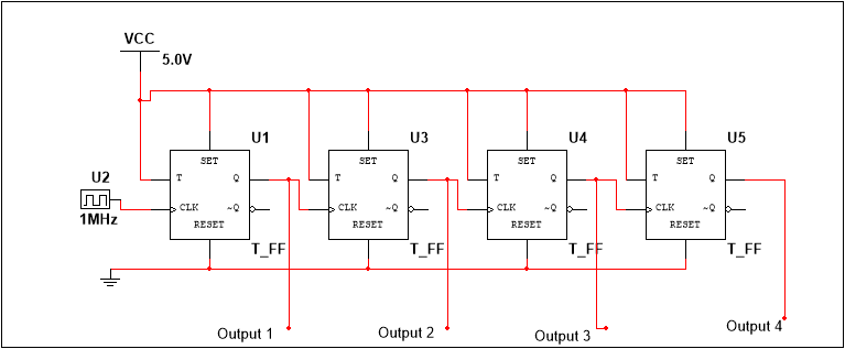
It consists of parallel arrangement of flip-flops wherein all the flip-flops are clocked simultaneously and in synchronization with the clock pulses. This is the reason propagation delay is independent of the number of flip-flops in the Synchronous counters.

These counters are equipped with combinational logic circuit as well, to ensure each flip-flop toggles at the right time. In synchronous counters, output of one flip-flop is given to input of another flip-flop.

Asynchronous or Ripple Counters

Click image to enlarge

Asynchronous Counter

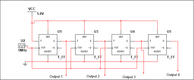
It consists of a cascaded arrangement of flip-flops wherein clock pulse of one flip-flop is driven by the output of its predecessor flip-flop. The number of flip-flops used determine the modulus of the counter, wherein the number of flip-flops depend upon the number of logic states in the counter, before it reaches its initial state.

The clock input is given to the first flip-flop. For a Modulo n counter, the clock input to the nth flip-flop is determined by the (n-1)th flip-flop output. Since clock of one flip-flop depends on the output of the previous flip-flop, it would change its state after a certain time delay which equals the propagation delays of both the flip-flops. For a Modulus n counter, the nth flip-flop will change its state after a delay of n times the propagation delay of one flip-flop.

Since the clock information ripples through the counter, it is known as a Ripple Counter. Also since the flip-flops do not change state in synchronization with the input clock, these counters are also known as Asynchronous counters.

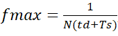
Since the final output would depend upon the propagation delay of each counters, there is a limit to the clock frequency, which is given as:

Where N is the number of flip-flops, td is propagation delay of one flip-flop and Ts is the strobe pulse width. Note that the propagation delay varies within different types of flip-flops.

Classification of Electronic Counters Based on Uses

Up/Down Counters:

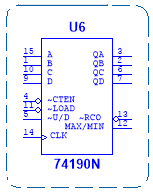
IC 74190 Up Down CounterAs the name suggests, these counters count in both ascending and descending order, i.e. in forward as well as reverse direction. While some counter ICs have separate clock input terminals for up and down counting (Example IC 74192 and IC 74192), some have only one clock input terminal and a control pin to select the required functioning (Examples: IC 74190, IC 74191).

Decade Counters:

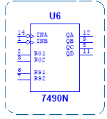
IC 7490 Decade Counter

A decade counter or a Module-10 counter goes through 10 unique output combination states until it resets. It consists of 4 flip-flops and requires additional circuitry to skip few states, toconvert the normal counter to a decade counter. It can count 16 possible states, out of which only 10 are used. Examples are 4017B, 7490N.

BCD Counter:

4 Bit BCD CounterIt is a special type of decade counter whose output is in accordance with the 8421 code.  The counter states are the binary equivalent of decimal numbers. Example is 74LS90.

Presettable Counters:

These are counters which can be pre-set to any initial count, with the help of the PRESET and CLEAR pins of the Flip-Flops. The flip-flops can be clocked asynchronously or synchronously. Presettable counters can be UP counters, DOWN counters or UP/DOWN counters.

These consist of additional input/output pins such as ‘Preset’ (To load any desired count), Parallel Load (PL) inputs (allows PRESET inputs to be loaded to the outputs), and Terminal Count (TC) outputs (becomes active when terminal count is reached.). Examples are IC74190, IC4191 and IC74193.

Ring Counter:

This counter is developed by modifying a shift register. The true output of the last flip-flop is fed back directly to the data input of the first flip-flop, thus generating a sequence of pulses. For example, for a D Flip-Flop shift register, the Q output of the last flip-flop is connected to the D input of the first flip-flop. These counters are used in digital system to generate control pulses.

Johnson Counter

This counter is a reverse of Ring Counter. In other words, feedback from the last flip-flop is fed inversely to the data input of the first flip-flop. For example, for a D Flip-Flop shift register, the ~Q output of the last flip-flop is fed to the D input of the first flip-flop. These can be used as Divide by n counters as well.

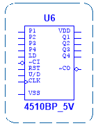
Practical Counter IC 4017:Counter IC 4017

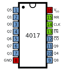
It is a 16 pin, CMOS logic Decade Counter cum Decoder, used mainly for low range counting applications. It can count from zero to ten, with decoded outputs, thus saving a lot of board space and time.

Functions of the IN/OUT PINS Of Counter IC 4017

Given below is the functionality of each of its pins.

Pins 1 to 7, 9 to 11: These are output pins of the IC, with each pin going high with corresponding decimal count. The status is as given below.

Pin 1: Goes HIGH when ‘5’ is the count.

Pin 2: Goes HIGH when ‘1’ is the count.

Pin 3: Goes HIGH when ‘0’ is the count.

Pin 4: Goes HIGH on count ‘2’.

Pin 5: Goes HIGH on count ‘6’

Pin 6: Goes HIGH on count 7.

Pin 7: Goes HIGH when count is ‘3’.

Pin 8: It is the ground pin, which is connected to LOW level voltage or to the ground.

Pin 9: Goes HIGH when count is ‘8’.

Pin 10: Goes HIGH when count is ‘4’.

Pin 11: Goes HIGH when count is ‘9’.

Pin 12: This pin is used for connecting with another Counter IC, to support larger counting order. Though we can achieve counts to 20 or more, by cascading multiple IC4017s together, it is advised not to cascade more than 3 ICs, in order to avoid occurrence glitches.

Pin 13: This is an Active LOW pin and is termed as the Disable pin. Once given a logic HIGH signal, it will disable the whole function of the IC, irrespective of the clock pulses.

Pin 14: This is the clock input pin. The input clock pulses are given to this pin and the count advances on rising or positive edge of the pulse.

Pin 15: This is the Active LOW reset pin, which once given a ‘HIGH’ logic signal would reset the IC.

Pin 16: This is the Power Supply pin which should be given a voltage from 3 Volts to 15 Volts.

Applications/Uses of Counters

Electronic counters are used in many digital electronic devices especially in digital clock and multiplexing. Most of their applications are listed below.

  • As object counters
  • Parallel to serial data conversion logic circuits
  • Analog to digital convertors.
  • Digital clocks
  • Frequency counters
  • Frequency divider circuits. (Where the Input frequency divided by 2)
  • Timers and Rate measurement. (Time circuits, Washing machines, Alarm clock etc)
  • Digital triangular wave generator.
  • Generating staircase voltage

This is a brief overview about different types of counters. Any other information regarding counters are welcome in the below section.

you may also read:

The post Counter and Types of Electronic Counters appeared first on Electrical Technology.


February 22, 2018 at 04:25AM by Department of EEE, ADBU: http://ift.tt/2AyIRVT
Calculate Lighting Fixture’s Beam Angle

ScreenHunter_01 Feb. 19 20.59

  • Calculate Lighting Fixture Beam Angle
  • Calculate Illumination at Surface from Beam Angle.
  • Calculate Lighting Fixture Lumen from Beam Angle.
  • Calculate Illuminated Diameter from Beam Angle.

FREE DOWNLOAD


February 19, 2018 at 09:08PM by Department of EEE, ADBU: http://ift.tt/2AyIRVT
Voice Recognition Based Home Automation System

Voice Controlled Home Automation System using 8051 Microcontroller

Voice Recognition Based Home Automation

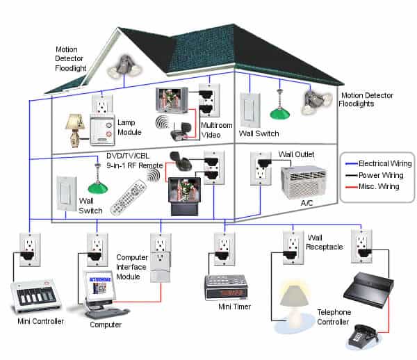
With the evolution of smart devices and various wireless communication technologies, it is now possible to leverage these techniques for the best possible benefits for human beings. One such benefit involves controlling of home appliances irrespective of the distance, saving time as well as energy. This smart controlling of home appliances is what we know as Home Automation same as industrial automation.

While there are various techniques like Wireless Communications, Internet of Things (IoT), Voice Recognition method, here we are going to have a small idea about how we can use Voice Recognition for Home Automation purpose.Practical Example of Voice Recognition Based..

Before that let us have a theoretical knowledge about Voice Recognition.

Voice Recognition

Voice recognition implies reception and interpretation of any linguistic dictation, by a machine or a program. It is the process of recognizing human speech and decoding it into text form.

It basically involves conversion of analog sound waves (vibrations in air caused by words spoken by human beings) to digital signals, which are decoded to appropriate words and then eventually sentences.

A speech recognition system generally consists of a speech capturing device (basically a microphone and a Analog to Digital Converter, which samples and digitizes the analog sound signals), a Digital Signal Processor (DSP) module (which process the digital signal to convert it from time domain to frequency domain, so as to retain the original information), a Preprocessed signal storage system (a memory card to carry out further task), Predefined speech patterns, stored in the memory as reference for matching, and a pattern matching algorithm for comparing the incoming speech signal with the reference speech pattern.

Voice Controlled Home Automation System using 8051 Microcontroller

It is noteworthy that a normal human being can produce speech at a rate of 10 sounds per second and the required information rate is 50 bits per second in the speech signal. This acoustic signal is converted to electrical signal by the microphone, and the analog signal is converted to digital signal.

Since this converted digital signal in time domain, is sampled at 16000 times per second, it is not suitable to locate the speech patterns. Hence it is converted to Frequency domain using Fast Fourier Transform (FFT) technique. This technique involves analyzing component after every 1/100th of a second and computing the frequency spectrum of each such component.

You may also read: Fully Automatic Water Level Controller using SRF04

Each such frequency graph or spectrum represents the segments of sounds made by the speech dictator. The computer or a controller matches the unknown speech segment with the stored phonetics of the language.

This pattern matching can be done using an acoustic phonetic approach (using the Hidden Markov Model, wherein the speech segment is matched with the phoneme per its probability), pattern recognition approach (unknown speech pattern compared with the reference speech pattern by determining the distance between the signals) and the Artificial Intelligence approach (based on utilization of basic knowledge sources).

The Proposed Model of Voice Controlled Home Automation

Here we have tried to build a small voice recognition based home automation system using wireless communication between two 8051 microcontrollers.

Disclaimer: The transmitter and receiver circuit presented here are theoretical and not tested practically. We have used Multisim which neither has the simulation model for HM2007 nor any Communication Model. Hence proper simulation for the system could not be possible.

The system involves processing of the voice command, from the user (at the microphone input) by the voice recognition IC, transmission and reception of the signal using Communication modules, controlled by the microcontroller. The microcontroller at the reception controls the switching of the bulb, based on the correct voice command from the transmitter system.

Now, let us have a brief idea about how the system would work.hm2007 voice recognition board

Figure 2: HM2007 Speech Recognition Board

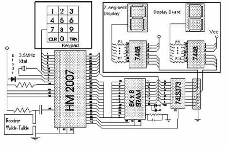
The heart of the speech recognition system involves the IC HM2007, which is a 48 pin IC providing speech recognition function. It works in Manual or CPU mode. It can recognize up to 20 words, each at a length of 1.92 seconds and operates at 9 to 15 Volts DC.Here we can use manual mode for HM2007.

Circuit Diagrams of Voice Recognition Home Automation System

Transmitter SectionTransmitter Section

Receiver SectionReceiver Section

Working of the System

1. The user gives voice input to the MICIN pin of HM2007 IC, through a microphone.

2. The RDY pin of the IC will be in active LOW state, indicating it is ready for training purpose.

3. The user presses “1” on the keypad and then the “TRAIN” key, before saying the target word (either “ON” or “OFF”)

4. The Memory Enable (ME) pin, connected to the corresponding pin of external SRAM, which stores the 8-bit data signal corresponding to the number

5. Once the voice input is detected, RDY pin goes HIGH and the IC starts the recognition process.

6. Result of the recognition process is given through the data bus to the 8051 Microcontroller.

7. The microcontroller (named uC1) transmits the data signal through the communication module.

8. At the receiver end, the microcontroller (named uC2) receives the data input and compares it with the stored command. Once both the data matches, the relay is operated (per the given command). If the data does not match, the microcontroller retransmits an error signal back.

9. The microcontroller uC1 receives this error signal and interrupts the on-going process, and displays the error information on the connected Liquid Crystal Display (LCD).

Limitations of Voice Recognition System

1. Continuous spoken words cannot be accepted by the system due to overlapping and hence there needs to be a silence or pause between two consecutive words. Thus, only isolated words would be feasible.

2. The system is a speaker dependent system. Too many speakers speaking simultaneously would result in overlapping of the signals and interruptions.

3. There is a limitation on vocabulary size as well. Languages with large vocabulary are difficult for pattern compared to languages with small vocabulary, since chances of having ambiguous words are less.

Irrespective of the above limitations, this system of controlling home appliances using voice recognition method would provide advantageous considering the fact it saves time as well as provides security.

I have presented a small model represented voice recognition based home automation, whereas on a large scale such system, once build on a large scale can be used for various applications.

Any other idea regarding controlling of home appliances using voice recognition is welcome in the below comments section.

You may also read:

The post Voice Recognition Based Home Automation System appeared first on Electrical Technology.


February 12, 2018 at 06:01AM by Department of EEE, ADBU: http://ift.tt/2AyIRVT
5 Telecommunication Systems Embbeded In Smart Grid Applications and Services

Power utilities use telecommunication systems either as a support for grid assets’ operation or as the enabler for voice communications among operating staff. The main objective of utility telecommunications is... Read more

Credit- Electrical Engineering Portal. Published by Department of EEE, ADBU: tinyurl.com/eee-adbu

Calculate Size of Neutral Earthing Transformer (NET)

Calculate Size of Neutral Earthing Transformer (NET) having following details

 Main Transformer Detail :

  • Primary Voltage(PVL): 33KV
  • Secondary Voltage (SVL): 11 KV
  • Frequency(f)=50Hz
  • Transformer Capacitance / Phase(c1)=0.006 µ Farad
  • Transformer Cable Capacitance / Phase(c2)= 0003 µ Farad
  • Surge Arrestor Capacitance / Phase(c3)=0.25 µ Farad
  • Other Capacitance / Phase(c4)=0 µ Farad

Required for Neutral Earthing Transformer:

  • Primary Voltage of the Grounding Transformer (Vp) =11KV
  • Secondary Voltage of the Grounding Transformer (Vs) =240V
  • Neutral Earthing Transformer % Reactance (X%)=40%
  • % of Force field condition for Neutral Earthing Transformer (ff) =30%
  • Neutral Earthing Transformer overloading factor(Of)=2.6
  • Neutral Earthing Transformer Base KV (Bv) =240V=0.240KV

Calculation:

  • Phase to Neutral Voltage (Vp1) =SVL /1.732
  • Phase to Neutral Voltage (Vp1) =11 /1.732 = 6.35 KV
  • Phase to Neutral Voltage under Force Field Condition (Vf) =Vp + (Vpxff)
  • Phase to Neutral Voltage under Force Field Condition (Vf)=6.35+ (6.35×30%) =8.26KV
  • Total Zero Sequence Capacitance (C)=C1+C2+C3+C4
  • Total Zero Sequence Capacitance (C)=0.006+0.0003+0.25+0=0.47730 µ Farad
  • Total Zero Sequence Capacitance Reactance to Ground (Xc)=10×6 / (2×3.14xfxC)
  • Total Zero Sequence Capacitance Reactance to Ground (Xc)=10×6 / (2×3.14x50x0.47730)=6672.35 Ω/Phase
  • Capacitive charging current/phase (Ic)=Vf / Xc
  • Capacitive charging current/phase (Ic)=8.26×1000 / 6672.35 = 1.24Amp
  • Total Capacitive charging current (It) =3xIc
  • Total Capacitive charging current (It) =3xIc =3×1.24 =3.71Amp
  • Rating of Neutral Earthing Transformer (Pr)=VpxIt
  • Rating of Neutral Earthing Transformer (Pr)=11×3.71=40.83KVA
  • Size of Neutral Earthing Transformer (P)=Pr/ Of
  • Size of Neutral Earthing Transformer (P)=40.83/ 2.6 = 16KVA
  • Residual Capacitive reactance (Xct) =Xc/3
  • l Capacitive reactance (Xct) = 6672.35 /3 =2224.12Ω
  • Turns Ratio of the Grounding Transformer (N)= Vp/Vs =11000/240 =45.83
  • Required Grounding Resistor value at Secondary side (Rsec)=Xct/NxN
  • Required Grounding Resistor value at Secondary side (Rsec)=2224.12 /45.83×45.83 =1.059 Ω
  • Required Grounding Resistor value at primary side (Rp)=Xct
  • Grounding Resistor value at primary side (Rp)= 2224.12Ω
  • Neutral Earthing Transformer Secondary Current=P/Vs
  • Neutral Earthing Transformer Secondary Current=16000/230= 65.44Amp
  • Neutral Earthing Transformer Secondary Resistor Current (for 30 Sec)=1.3xItxN
  • Neutral Earthing Transformer Secondary Resistor Current (for 30 Sec)=1.3×3.71×45.83=221.18Amp
  • Neutral Earthing Transformer Reactance Base(Base X)=BvxBv/P/1000
  • Neutral Earthing Transformer Reactance Base(Base X)=0.24×0.24/11/1000=3.67Ω
  • Neutral Earthing Transformer Reactance in PU (Xpu)=X% =40%=0.04Pu
  • Neutral Earthing Transformer Reactance (X)=Xpu x BaseX
  • Neutral Earthing Transformer Reactance (X)=0.04×3.67 =0.15Ω
  • Neutral Earthing Transformer X/R Ratio=X/Rsec
  • Neutral Earthing Transformer X/R Ratio=0.15/1.059 = 0.14
  • Fault current through Neutral (single line to ground fault) (If)=Vp1/Rp
  • Fault current through Neutral (single line to ground fault) (If)=6.35×1000/2224.12 =2.86Amp
  • Short time Rating of Neutral Earthing Transformer=PxOf =16×2.6 =41KVA

Result:

  • Rating of Neutral Earthing Transformer (P)=40.83/ 2.6 = 16KVA
  • Short time Rating of Neutral Earthing Transformer=41KVA
  • Ratio of Neutral Earthing Transformer =11000/240 Volt
  • Neutral Earthing Transformer Secondary Current=65.44A
  • Required Grounding Resistor value at primary side (Rp)=2224.12Ω
  • Required Resistance at secondary side (Rsec)= 1.059Ω
  • Neutral Earthing Transformer Secondary Resistor Current (for 30 Sec)= 221.2A


February 06, 2018 at 07:02PM by Department of EEE, ADBU: http://ift.tt/2AyIRVT
What is Fuzzy Logic System – Operation, Examples, Advantages & Applications

What is Fuzzy Logic System?

Introduction to Fuzzy Logic

Fuzzy Logic is a logic or control system of an n-valued logic system which uses the degrees of statedegrees of truth“of the inputs and produces outputs which depend on the states of the inputs and rate of change of these states (rather than the usual “true or false” (1 or 0), Low or High Boolean logic (Binary) on which the modern computer is based). It basically provides foundations for approximate reasoning using imprecise and inaccurate decisions and allows using linguistic variables. What Is Fuzzy Logic System

It was developed in 1965, by Professor LoftiZadeh, at University of California, Berkley. The first application was to perform computer data processing based on natural values.

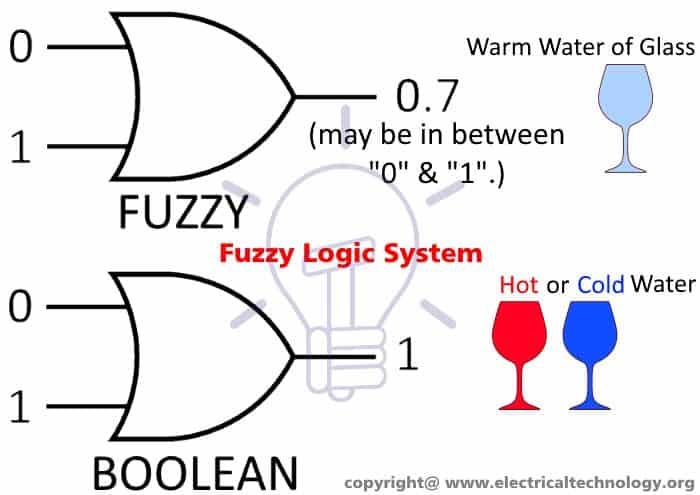
In more simple words, A Fuzzy logic stat can be 0, 1 or in between these numbers i.e. 0.17 or 0.54.

For example, In Boolean, we may say glass of hot water ( i.e 1 or High) or glass of cold water i.e. (0 or low), but in Fuzzy logic, We may say glass of warm water  (neither hot nor cold).

let see another example,

Boolean Logic : Yes or No (0,1)

Fuzzy Logic: Certainly Yes, Possibly No, Can’t Say, Possible Yes etc.

Basic Architecture of Fuzzy Logic System

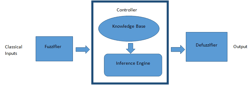
A Fuzzy Logic System consists of the following modules:

Fuzzy control system

1. Fuzzifier: It accepts the measured variables as input and converts the numerical values to linguistic variables. It transforms the physical values as well as the error signals to a normalized fuzzy subset which consists of an interval for the input values range and membership functions that describe the probability of state of the input variables. The input signal is basically split into five states as in – Large Positive, Medium Positive, Small, Medium Negative and Large Negative.

2. Controller: It consists of the knowledge base as well as the inference engine. The knowledge Base stores the membership functions and the fuzzy rules, obtained by knowledge of system operation per the environment. The inference engine performs processing of the obtained membership functions and fuzzy rules. In other words, the inference engine assigns outputs based on linguistic information.

3. Defuzzifier: It performs the reverse process of the Fuzzifier. In other words, it converts the fuzzy values to the normal numerical or physical signals and sends them to the physical system to control the system operation.

Fuzzy Logic System Operation

Fuzzy operation involves use of fuzzy sets and membership functions. Each fuzzy set is a representation of a linguistic variable that defines the possible state of output. Membership function is the function of a generic value in a fuzzy set, such that both the generic value and the fuzzy set belong to a universal set.

The degrees of membership of that generic value in the fuzzy set determines the output, based on the principle of IF-THEN. The memberships are assigned based on the assumption of outputs with the help of inputs and rate of change of inputs. A membership function is basically a graphical representation of the fuzzy set.

Consider a value ‘x’ such that x€X for all interval [0,1] and a fuzzy set A, which is a subset of X. Membership function of ‘x’ in the subset A is given as : fA(x). Note that ‘x’ denotes the membership value.

Given below is the graphical representation of fuzzy sets.Graphical Representation of Fuzzy Set

While the x-axis denotes the universal set, the y-axis denotes the membership degrees. These membership functions can be triangular, trapezoidal, singleton or Gaussian in shape.

Practical Fuzzy System Example

Let us design a simple fuzzy control system to control operation of a washing machine such that the fuzzy system controls the washing process, water intake, wash time and spin speed.

The input parameters here are the volume of clothes, degree of dirt and type of dirt. While the volume of clothes would determine the water intake, the degree of dirt in turn would be determined by the transparency of water and the type of dirt is determined by the time at which the water color remains unchanged.

Step 1: The first step would involve defining linguistic variables and terms. For the inputs, the linguistic variables are as given below

  1. Type of Dirt: {Greasy, Medium, Not Greasy }
  2. Quality of Dirt: {Large, Medium, Small }

For output, the linguistic variables are as given below

Wash Time: {Short, Very Short, Long, Medium, Very Long}

Step 2: The second step involves construction of membership functions.

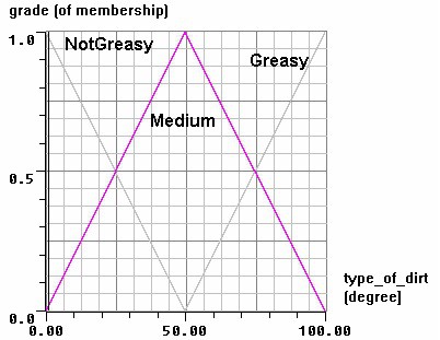
Given below are graphs determining membership functions for the two inputs are as given below:

Membership Functions for Quality of Dirt

Membership Functions for Quality of DirtMembership Functions for Type of Dirt

Membership Functions for Type of Dirt

Step 3: The third step involves developing a set of rules for the knowledge base. Given below are the set of rules using IF-THEN logic

  1. IF quality of dirt is Small AND Type of dirt is Greasy, THEN Wash Time is Long.
  2. IF quality of dirt is Medium AND Type of dirt is Greasy, THEN Wash Time is Long.
  3. IF quality of dirt is Large and Type of dirt is Greasy, THEN Wash Time is Very Long.
  4. IF quality of dirt is Small AND Type of dirt is Medium, THEN Wash Time is Medium.
  5. IF quality of dirt is Medium AND Type of dirt is Medium, THEN Wash Time is Medium.
  6. IF quality of dirt is Large and Type of dirt is Medium, THEN Wash Time is Medium.
  7. IF quality of dirt is Small AND Type of dirt is Non-Greasy, THEN Wash Time is Very Short.
  8. IF quality of dirt is Medium AND Type of dirt is Non-Greasy, THEN Wash Time is Medium.
  9. IF quality of dirt is Large and Type of dirt is Greasy, THEN Wash Time is Very Short.

Step 4: The fuzzifier which initially had converted the sensor inputs to these linguistic variables, now applies the above rules to perform the fuzzy set operations (like MIN and MAX) to determine the output fuzzy functions. Based upon the output fuzzy sets, the membership function is developed.

Step 5: The final step is the defuzzification step where the Defuzzifier uses the output membership functions to determine the output washing time.

Note: The above-mentioned example is just a simple theoretical example. The practical model would be more complex and deploys Neuro-Fuzzy Logic for the same.

Applications

  1. Fuzzy Logic system can be used in Automotive systems, for applications like 4-Wheel steering, automatic gearboxes etc.
  2. Applications in the field of Domestic Applications include Microwave Ovens, Air Conditioners, Washing Machines, Televisions, Refrigerators, Vacuum Cleaners etc.
  3. Other applications include Hi-Fi Systems, Photo-Copiers, Humidifiers etc.

Advantages

  • A Fuzzy Logic System is flexible and allow modification in the rules.
  • Even imprecise, distorted and error input information is also accepted by the system.
  • The systems can be easily constructed.
  • Since these systems involve human reasoning and decision making, they are useful in providing solutions to complex solutions in different types of applications.

While there are numerous other advantages of this concept, still the loophole lies in the ability of the logic system for complex and ultra-accurate systems. This is a basic knowledge I had about Fuzzy Logic System and any other inputs are welcome in the below comments section.

You may also read

The post What is Fuzzy Logic System – Operation, Examples, Advantages & Applications appeared first on Electrical Technology.


February 06, 2018 at 08:04AM by Department of EEE, ADBU: http://ift.tt/2AyIRVT
Substation splitting and CB autoclosing for limitation of short-circuit currents

In this article, we describe method and technique of substation splitting and use of circuit breaker autoclosing that may be used for the control and limitation of the magnitude of... Read more

Credit- Electrical Engineering Portal. Published by Department of EEE, ADBU: tinyurl.com/eee-adbu